B network connection, C switches – AGI Security GV-CONCT User Manual
Page 19
GV-AS100 Controller
9
1
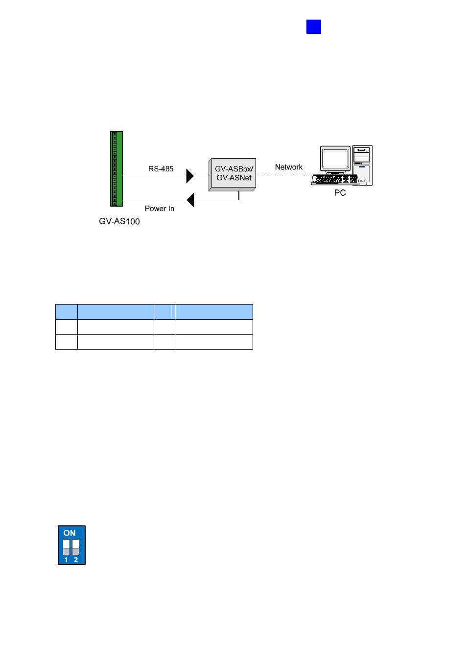
1.2.4.B Network Connection
The figure below illustrates the network connection to the computer. For this connection, the
optional product GV-ASBox or GV-ASNet is required.
Figure 1-7
Connect two power wires and two RS-485 wires from GV-ASBox/GV-ASNet to GV-AS400.
The table below shows the pin assignments of related connectors on GV-AS100.
Pin Function
Pin Function
1
Power In 12V
3
RS-485 A+
2 GND
4 RS-485
A-
Also see 4.1.4.A Connecting GV-AS100/GV-AS110.
1.2.4.C Switches
Switch 1: When Switch 1 is ON, GV-AS100 can connect to GV-ASManager, GV-ASBox or
GV-ASNet. When Switch 1 is OFF, the connection is unavailable. By default Switch 1 is set
to ON.
Switch 2: When the RS-485 connection between GV-AS100 and computer is longer than
600 meters (1968.50 feet), the RS-485 signal may become weak. In this case, turn Switch 2
ON to have a 120-Ohm resistor.
Figure 1-8