H compressor bypass valve, Compressor bypass valve assembly installation – Paxton Superchargers Shelby Mustang GT User Manual
Page 48
P/N: 4809660
©2007 Paxton Automotive
All Rights Reserved, Intl. Copr. Secured
27FEB07 v1.0 05-07ShelbyMusGT(4809660v4.0)
36
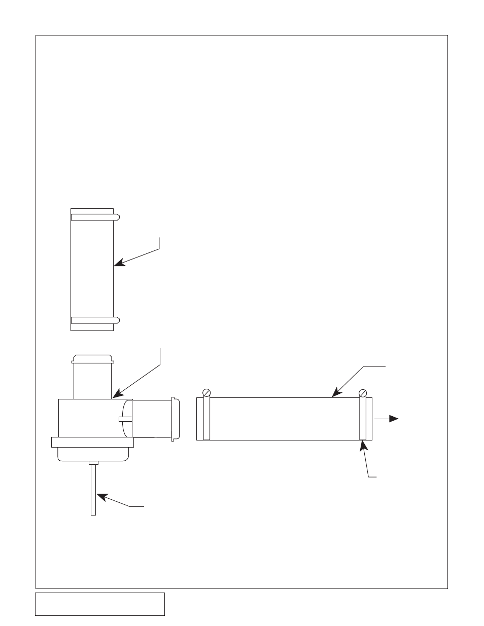
Fig. 8H-a
8.
CHARGE AIR COOLER INSTALLATION
11" x Ø1" HOSE
(TRIM TO FIT)
TO DISCHARGE
TUBE
13" x Ø1" HOSE
(TRIM TO FIT)
TO MANIFOLD PRESSURE/VACUUM
#16 HOSE CLAMPS
BYPASS
VALVE
TO INLET
DUCT
H.
COMPRESSOR BYPASS VALVE
ASSEMBLY INSTALLATION
1.
Assemble the bypass using a piece of
1" hose cut to 11" long and a piece cut
to 13" long and four #16 hose clamps.
2.
Attach the 11" piece of hose to the inlet
of the bypass and secure with a clamp.
3.
Secure the 13" piece to the outlet of the
valve, securing it with a clamp. (See
Fig. 8H-a.)
4.
Attach the bypass assembly to the
charge cooler. The 11" long piece will
be attached to the charge cooler. Secure
with clamps. Leave the 13" long sec-
tion open for future attachement to the
air inlet.
5.
Attach a length of 5/32" vacuum hose
to the bypass valve and route to the
vacuum port of the fuel rail sensor.
6.
Cut a section of the factory hose and
install the vacuum TEE that is provid-
ed. (See Fig. 10-b on page 40.)
7.
Attach the vacuum hose from the
bypass valve to the TEE.