Paxton Superchargers Shelby Mustang GT User Manual
Page 16
P/N: 4809660
©2007 Paxton Automotive
All Rights Reserved, Intl. Copr. Secured
27FEB07 v1.0 05-07ShelbyMusGT(4809660v4.0)
4
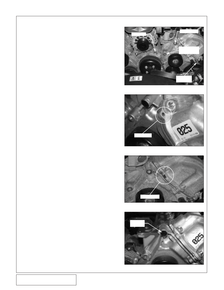
Fig. 1-o
Fig. 1-r
Fig. 1-r1
Fig. 1-s
STUD BOLT
MODIFY STUD
REMOVE 13mm
HEADED BOLT
REMOVE
STUD BOLT
P.
Using a 1/2" ratchet, release the tension from the
accessory drive belt and remove it from the car.
This drive belt will be replaced with a longer one
later in the installation.
Q.
Locate and remove the stud bolt that secures the
alternator in place as well as the bolt located to
the right of the alternator. (See Fig. 1-o.) Using a
15mm socket or wrench, remove the nut that
secures the capacitor, resistor and coolant hose
support bracket to the stud bolt. Using an 18mm
socket or wrench, remove the stud bolt, it will be
modified and replaced in a later step.
R.
There is a small tab that secures the wiring har-
ness in place on the valve cover that will need to
be removed to gain clearance for the supercharger
belt. This tab is best removed with a small air saw
but a grinder will work. After removal, smooth the
area to prevent damage to the belt. (See Figs. 1-r,
1-r1.)
S.
As seen in Fig. 1-o, the upper bolt is removed
from the timing chain cover. This bolt will have to
be modified by cutting off the threaded end where
the resistor attaches. Modify and reinstall the bolt.
(See Fig. 1-s.)
T.
Disconnect the plug to the cam position sensor.
Remove the wiring harness from the retaining
clips that hold it to the valve cover. Move the har-
ness out of the way. This harness will have to be
relocated to gain clearance for the supercharger.
REMOVE TAB
TAB REMOVED
1.
PREPARATION/REMOVAL, cont’d
MODIFIED
STUD BOLT