D*ap4 – Junger Audio D*AP4 FLX / D*AP4 LM Edition User Manual
Page 9
D*AP4
4
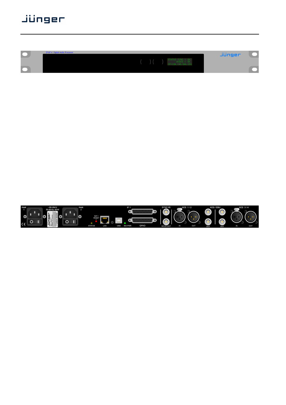
D*AP4 front panel view
The front panel of the D*AP4 has a 3 line status display and two hidden touch buttons ~ 2.5cm left of the
display. Button 1 = Home will switch back to the power up display no matter which display level you are in.
Button 2 controls the multi level display:
Level 1
Power up display [Device type, firmware version]
Level 2
Status [OK / Error] / Device Name / IP address
Level 3
IN / OUT peak meter
Level 4
Program 1 Out - short term loudness
Level 5
Program 2 Out - short term loudness
Level 6
Program 1 Out - integrated loudness and integration time
Level 7
Program 2 Out - integrated loudness and integration time
The measures of the loudness displays depend on the setup of the respective loudness mode
(see AUDIO PROCESSOR > SETUP > Loudness Mode).
Display background
Green = device status OK
color
Red
= device status ERROR
D*AP rear view
For fail safe operation, the D*AP4 provides two independent power supplies. These power supplies operate
in load balance. The status of both PSUs are combined with other status information and displayed as back
light color the front panel display.
STATUS
shows the status of the device controller.
INIT /
pressing the INIT button briefly will warm start the device controller.
RESET
Holding down the button until the STATUS LED flashes 5 times will initialize the
D*AP4 to factory default
LAN
RJ45 socket for Ethernet connection to a LAN
USB
USB 2.0 type B socket to connect the built in USB >> serial converter with an
external PC
ISO-PWR
lights up if the isolated 5V power supply for GPI /O application is turned on
Interface 1
slot to mount one of the optional interface boards (SDI, AES, analog)
GPI/O
25pin Sub-D female connector to interface with the 8 optical isolated general
purpose inputs and 8 solid state relay closure outputs
SYNC IN
75Ohm BNC connector to connect with external sync sources
WCLK-OUT
75Ohm BNC connector to synchronize external devices to the D*AP4 internal
word clock
AES 1/2 IN / OUT
AES3 (XLR) and AES3id (BNC) input (selectable via GUI) / output (parallel)
AES 3/4 IN / OUT
AES3 (XLR) and AES3id (BNC) input (selectable via GUI) / output (parallel)