D*ap4 – Junger Audio D*AP4 FLX / D*AP4 LM Edition User Manual
Page 42
D*AP4
37
The routing example on the left hand side shows that the AES inputs 1,2 are connected to the inputs
DSP 1,2 (label
1L/1R)
of the DSP. The outputs DSP 1,2 (label
1L/1R
) are connected with the inputs
DELAY 1,2 and with the outputs AES 1,2 (label
L, R
). The outputs DELAY 1,2 finally are connected with
the outputs AES 3,4 (label
L,R
).
Important Note! If a different optional interface board is installed the matrix will be expanded by the
pre-defined number of I/Os with their labels:
SDI
[O_DAP_SDI_a]
DEM 1 … DEM 16 and EMB 1… EMB 16
MADI
[O_DAP_MB_a /
MDIN 1 … MDIN 8 and MDOUT 1 … MDOUT 8
O_MO_MM_a / _MS_a]
DANTE
[O_DAP_DANTE_a]
DTIN 1 ... DTIN 8 and DTOUT 1 ... DTOUT 8
4 Ch ANALOG I/O
[O_DAP_ADDA_a]
ANL 1 … ANL 4 and ANL 1 … ANL 4
8 Ch ANALOG out
[O_DAP_8DA_a]
ANL 1 ... ANL 8
AES
[O_DAP_AES_a]
AES 1 … AES 8 and AES 1 … AES 8
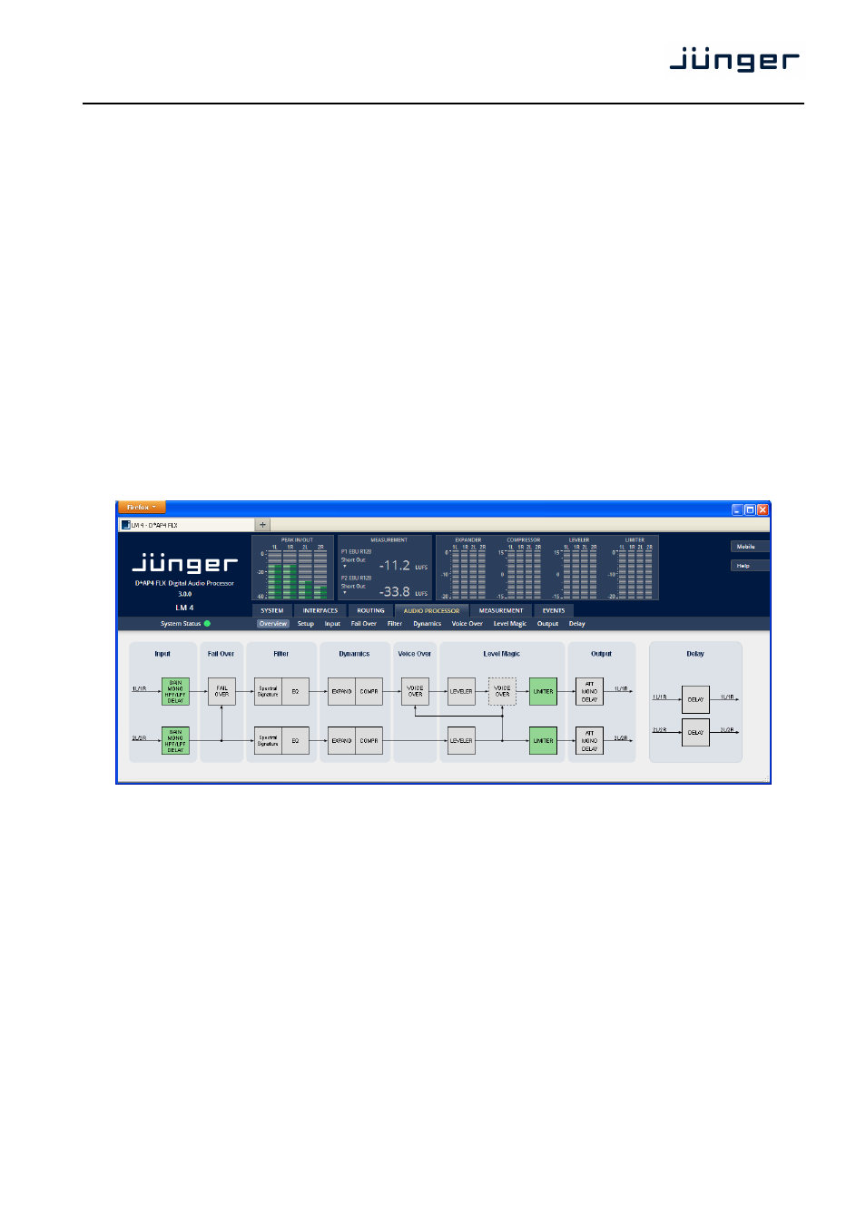
Setup GUI – AUDIO PROCESSOR - Overview
The overview shows the actual signal flow and the audio processor blocks, rendered by the DSPs.
The processing blocks in use, which may be activated from their individual setup panes, will be indicated in
green. I.e. blocks shown in grey are not activated by the user.
To navigate through the various processing blocks you may either click on the graphical block above
or use the tabs provided in the navigation bars below the bar graph displays.