Usb-uart, Usb-uart –31 – Altera Cyclone V E FPGA Development Board User Manual
Page 39
Chapter 2: Board Components
2–31
Components and Interfaces
March 2013
Altera Corporation
Cyclone V E FPGA Development Board
Reference Manual
USB-UART
The development board supports UART interface through a USB connector using
Silicon Labs CP2104 USB-to-UART bridge. To facilitate host communication with
CP2104, you are required to use the USB-to-UART bridge Virtual COM Port (VCP)
drivers.
f
The VCP drivers are available at:
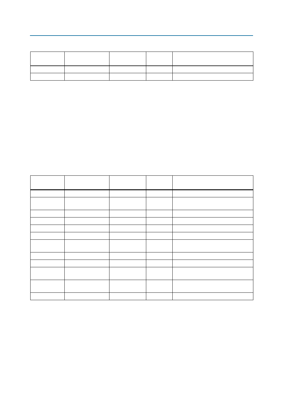
lists the USB-UART pin assignments, signal names, and functions. The
signal names and types are relative to the Cyclone V E FPGA in terms of I/O setting
and direction.
16
UART_RXD
AG6
3.3-V
Receive data
13
UART_CTS
AF8
3.3-V
Clear to send
Table 2–22. RS-232 Serial UART Schematic Signal Names and Functions
Board
Reference (U20)
Schematic
Signal Name
Cyclone V E FPGA
Pin Number
I/O Standard
Description
Table 2–23. USB-UART Schematic Signal Names and Functions
Board
Reference (U20)
Schematic
Signal Name
Cyclone V E FPGA
Pin Number
I/O Standard
Description
1
USB_UART_RI
AD12
2.5-V
Ring indicator control input (active low)
24
USB_UART_DCD
AD13
2.5-V
Data carrier detect control input (active
low)
22
USB_UART_DSR
V12
2.5-V
Data set ready control input (active low)
21
USB_UART_RXD
AF10
2.5-V
Asynchronous data input (UART receive)
19
USB_UART_RTS
AE12
2.5-V
Ready to send control output (active low)
12
USB_UART_GPIO2
AE13
2.5-V
User-configurable input or output.
23
USB_UART_DTR
AE10
2.5-V
Data terminal ready control output (active
low)
20
USB_UART_TXD
W12
2.5-V
Asynchronous data output (UART transmit)
18
USB_UART_CTS
AJ1
2.5-V
Clear to send control input (active low)
15
USB_UART_SUSPENDn
—
2.5-V
Pin is logic low when the CP2104 is in the
USB suspend state.
17
USB_UART_SUSPEND
—
2.5-V
Pin is logic high when the CP2104 is in the
USB suspend state.
9
USB_UART_RSTn
—
2.5-V
Device reset