Board settings dip switch, Jtag chain control dip switch, Cpu reset push button – Altera Cyclone V E FPGA Development Board User Manual
Page 25
Chapter 2: Board Components
2–17
Setup Elements
March 2013
Altera Corporation
Cyclone V E FPGA Development Board
Reference Manual
f
For more information about the default settings of the DIP switches, refer to the
Board Settings DIP Switch
The board settings DIP switch (SW4) controls various features specific to the board
and the MAX V CPLD 5M2210 System Controller logic design.
Table 2–8
lists the
switch controls and descriptions.
JTAG Chain Control DIP Switch
The JTAG chain control DIP switch (SW2) either removes or includes devices in the
active JTAG chain. The Cyclone V E FPGA is always in the JTAG chain.
Table 2–9
lists
the switch controls and its descriptions.
CPU Reset Push Button
The CPU reset push button, CPU_RESETn (S4), is an input to the Cyclone V E FPGA
DEV_CLRn
pin and is an open-drain I/O from the MAX V CPLD System Controller.
This push button is the default reset for both the FPGA and CPLD logic. The MAX V
CPLD 5M2210 System Controller also drives this push button during power-on-reset
(POR).
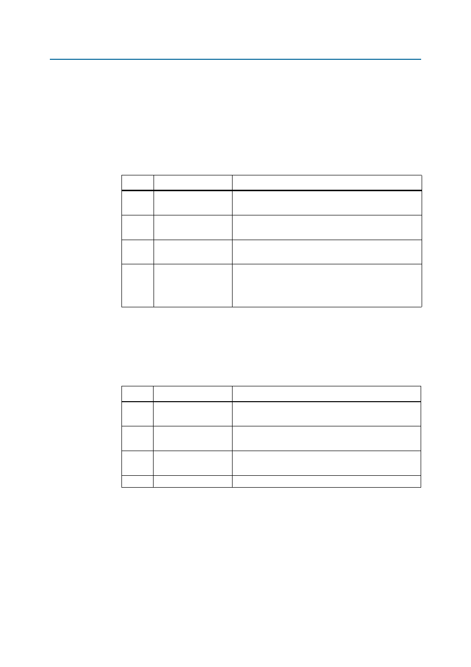
Table 2–8. Board Settings DIP Switch Controls
Switch
Schematic Signal Name
Description
1
CLK_SEL
ON : Select programmable oscillator clock
OFF : Select SMA input clock
2
CLK_ENABLE
ON : Disable on-board oscillator
OFF : Enable on-board oscillator
3
FACTORY_LOAD
ON : Load the user design from flash at power up
OFF : Load the factory design from flash at power up
4
SECURITY_MODE
ON : Embedded USB-Blaster II sends FACTORY command at
power up.
OFF : Embedded USB-Blaster II does not send FACTORY
command at power up.
Table 2–9. JTAG Chain Control DIP Switch
Switch
Schematic Signal Name
Description
1
5M2210_JTAG_EN
ON : Bypass MAX V CPLD 5M2210 System Controller
OFF : MAX V CPLD 5M2210 System Controller in-chain
2
HSMC_JTAG_EN
ON : Bypass HSMC port
OFF : HSMC port in-chain
3
FAN_FORCE_ON
ON : Enable fan
OFF : Disable fan
4
RESERVED
Reserved