Hanna Instruments HI 8050 User Manual
Page 73
73
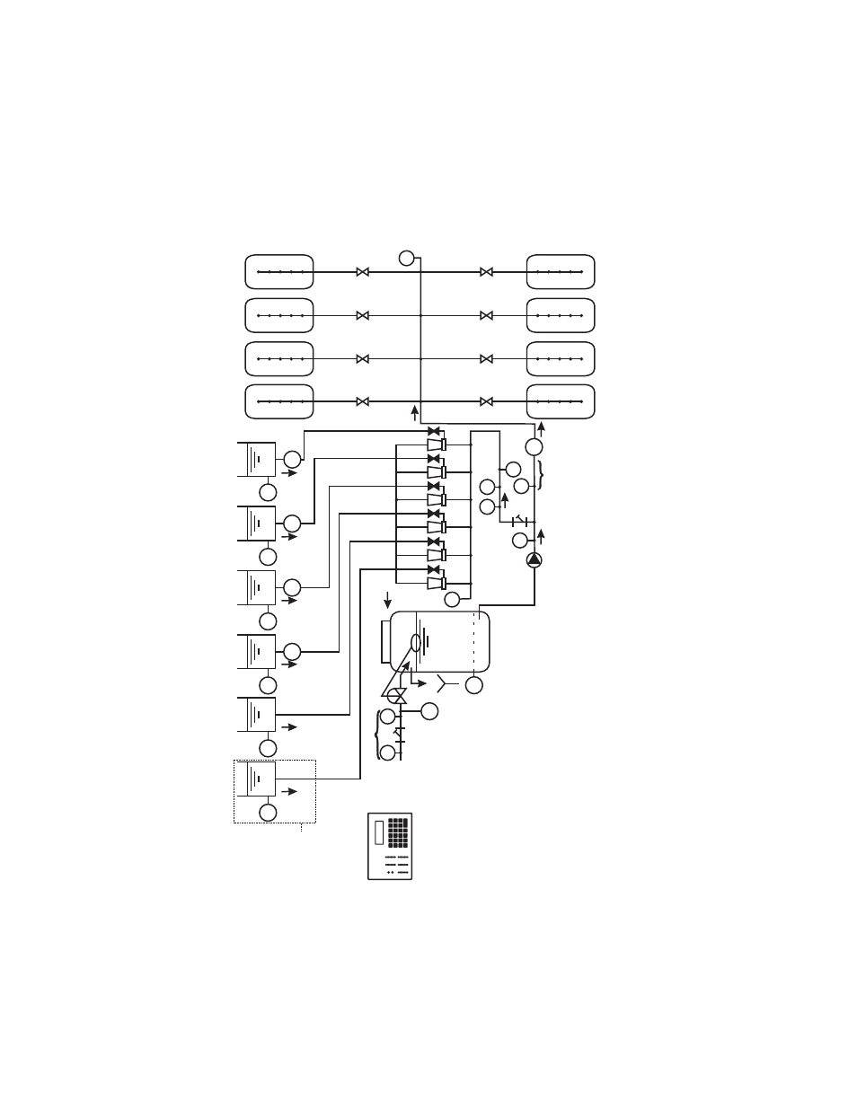
BLOCK DIAGRAM
Typical installation of an irrigation system using the 8050/8060 Controller
Fer
tilizer
and
Ir
rigation
Controller
EC
in
FC
P11
differential
p
resostate
F
ilter
1
HLC
W
a
ter
supply
P12
IP
P0
F
ilter
2
P1
EF1
EF2
EF3
EF4
Sv1
S1
Sv5
S5
Sv2
S2
Sv6
S6
Sv3
S3
Sv7
S7
Sv4
S4
Sv8
S8
P2
C
Counter
Mixing
tank
Fer
tilizer
1
Fer
tilizer
2
Fer
tilizer
3
Fer
tilizer
4
F
ilter
1
F
ilter
2
LA
T
LA
K
LMT
LFT
HLC
P11,
P12,
P21,
P22
P0,
P1,
P2
IP
pH1
EC1,
EC
EA
EK
EF1...EF4
C
Sv1...Sv8
S1...S8
FC1..FC4
in
-
water
supply
filter
-
second
filter
(in
front
of
sensor)
-
low
level
acid
tank
-
low
level
alk
a
line
tank
-
low
level
mixing
tank
-
low
level
fer
tilizers
tank
-
h
igh
level
control
for
mixing
tank
-
d
ifferential
p
resostates
-
p
ressure
indicators
-
ir
rigation
pump
-
p
H
sensor
-
conductivity
sensors
-
e
lectrovalve
for
acid
-
e
lectrovalve
for
a
lk
aline
-
e
lectrovalve
for
fer
tilizer
-
flow
counter
-
sectors
e
lectrovalves
-
sectors
-
fer
tilizer
counters
FC
FC
FC
LMT
LFT
LFT
LFT
LFT
Acid
LA
T
EA
EC1
pH1
P21
differential
presostate
P22
Alk
aline
LA
K
EK
Only
for
HI
8060