14 replacement of parts, 14 gas valve – Glow-worm Betacom C User Manual
Page 60
60
14 Replacement of parts
14585
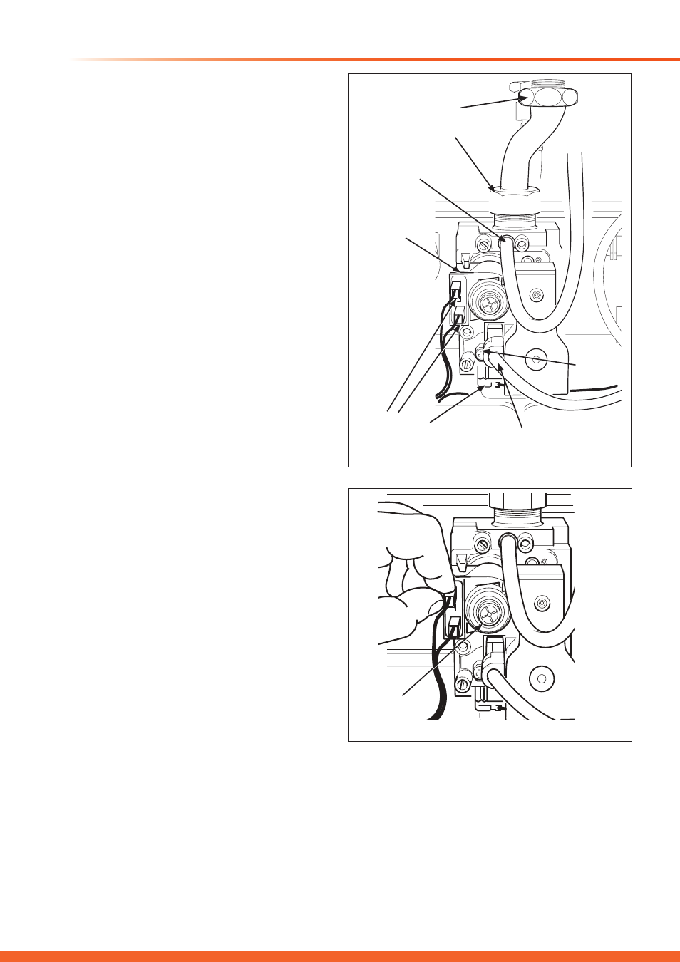
Diagram 14.14
14.14 Gas valve
For access, refer to section 14.0.
Ensure that gas supply to boiler is turned off.
Refer to diagrams 14.14 and 14.15.
Disconnect the electrical connections to the modulating coil.
Remove the screw to disconnect the gas valve electrical plug.
Release the connections from gas valve and manifold inlet,
Remove the sensing tube.
Retaining the washers for use on reassembly.
Release the main gas connection between the gas valve
supply pipe and gas inlet isolation valve, retaining the washer
for use on reassembly, see diagram 14.15.
Remove the gas valve’s two securing screws and washers
from the underside of the boiler, see diagram 14.17.
Rotate the gas pipe and withdraw gas valve assembly.
Refit in reverse order to removal, the polarity of the wires to
the modulating coil is not important.
Check gas soundness and correct boiler operation
Following replacement the maximum and minimum settings
for natural gas must be checked to ensure they are 12.5 mbar
/ 2.5 mbar for the Betacom 24 and 14 mbar / 2.3 mbar for
Betacom 30 respectively.
Check the gas valve settings and re-calibrated by the
following method if required:
Minimum setting
Remove the sensing tube from the gas valve.
Remove one lead from the modulating gas valve coil, see
diagram 14.15.
Refer to diagram 14.16.
Connect a suitable pressure gauge to the pressure outlet of
the gas valve.
Turn the boiler’s function switch to the ‘Winter’ position.
(Heating and Hot Water), see diagram 11.4
Turn the central heating temperature control to maximum
setting.
Remove the protective cover from the gas valve adjuster.
Turn the inner screw using a screwdriver, clockwise: to
increase the pressure setting, anticlockwise: to decrease the
pressure setting.
After correct adjustment see, ‘Boiler specification section’
page 8, re-connect the electrical connector and protective
cover and replace the combustion cover to the boiler.
Maximum setting
Remove the sensing tube from the gas valve, see diagram
14.14.
Remove the protective cover from the gas valve adjuster.
Push the ball inside the modulating gas valve coil using a
sharp pointed tool.
Turn the nut with a 10mm spanner (keeping the ball in without
any rotation) clockwise: to increase the pressure setting,
anticlockwise: to decrease the pressure setting.
After correct adjustment see, “Boiler specification” section,
page 8.
Finally, replace the sensing tube to the gas valve.
ELECTRICAL
AND EARTH
CONNECTIONS
ELECTRICAL
PLUG
SCREW
SENSING TUBE
MODULATING
COIL
GAS VALVE AND
MANIFOLD INLET
CONNECTIONS
Diagram 14.15
15524
GAS VALVE
ADJUSTER