11 commissioning, 3 control panel functions, diagram 11.4, 3 commissioning – Glow-worm Betacom C User Manual
Page 39: 4 initial lighting, Diagram 11.4
39
1
2
3
4
bar
0
1
0
22
21
20
19
18
17
16
15
14
13
12
11
10
9
8
7
6
5
4
3
2
1
24
23
ON
30
40
50
60
70
80
90
bar
11 Commissioning
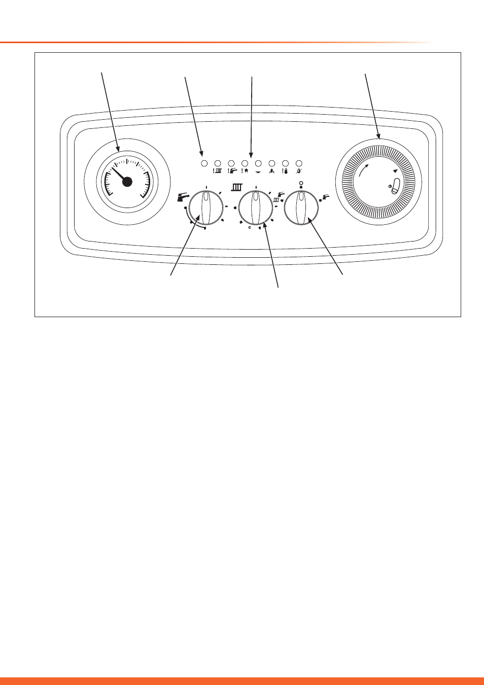
11.3 Control Panel Functions, diagram 11.4.
Central heating and domestic hot water temperature
controls: The boiler’s integral control unit monitors and
adjusts both the boiler’s hydraulic circuit and D.H.W. water
outlet temperatures by means of sensors located on the
CH heating and D.H.W. flow outlets. The sensors electrical
resistance, which is dependant on temperature, determines
the current passing through the control potentiometers
located on the control panel. The respective potentiometer
control dial allows manual setting of the maximum required
temperature (reference value) being between 30º and 85ºC
for CH heating and 35º and 64ºC for D.H.W. When the boiler
operates in heating or D.H.W. mode, the current received is
compared to the manually set reference value. The difference
of the two values operates the modulation of the gas valve
adjusting the useful heat output generated and stabilising the
temperature to within ±1ºC.
Re-set function: Should the boiler lock out at any time,
please check the gas supply and ionisation probe position, the
boiler may be re-started by switching to standby “O” position
waiting 15-30 seconds.
Switching back to its previous position once the fault has been
eliminated.
Function switch: The three position switch allows the boilers
operation to be set to ‘Stand-by’ (centre position), ‘Heating
+ D.H.W.’ (left hand position) or ‘D.H.W. only’ (right hand
position).
14333
Diagram 11.4
11.3 Commissioning
The Betacom 24c and 30c boilers have been tested and pre-
set at the factory and is dispatched with its on board controls
set to provide a maximum central heating and D.H.W. output.
Consequently, once all the connections have been made and
the boiler has been filled with water to the designed system
operating pressure, the boiler may be fired prior to adjusting
it’s on board parameters to match the heating systems
requirements.
11.4 Initial Lighting
Prior to firing: Check that the electrical supply to the boiler
is ‘On’ (The green boiler ‘Stand by’ indicator will light) and the
gas service isolation valve is in the open position, see diagram
11.1.
Set the boiler’s central heating and domestic hot water
temperature controls to maximum by turning them fully
clockwise.
Set the external room thermostat (if fitted) to maximum and
open the thermostatic radiator valves to maximum.
Switch the boilers function switch to the central heating and
domestic hot water position. The boiler’s control unit will
now automatically carry out pre-ignition safety checks before
igniting the burner.
TIMER
DISPLAY
STANDBY
INDICATOR
PRESSURE GAUGE
FUNCTION
SWITCH
CENTRAL HEATING
TEMPERATURE
CONTROL
DOMESTIC HOT WATER
TEMPERATURE
CONTROL