11 commissioning, 1 preliminaries - all systems, 2 filling the system – Glow-worm Betacom C User Manual
Page 38
38
11 Commissioning
IMPORTANT
:
At the time of commissioning, complete all
relevant sections of the Benchmark Checklist located in the
centre pages of this document.
11.1 Preliminaries - All Systems
Do Not operate the boiler without water.
The commissioning should be carried out by a
competent
person approved at the time by the Health and Safety
Executive and in accordance with the current issue of
BS6798.
Make sure that the system has been thoroughly flushed
out with cold water and that all cleanser if used has been
removed.
With the gas service isolation valve closed, with no demand
from any external controls and the power supply to the boiler
switched off, test for gas soundness and purge air from the
gas supply.
11.2 Filling the System
On completion of the boiler installation and ensuring that all
water connections are correctly made the boiler may be filled
with water via the filling loop (not supplied with the boiler).
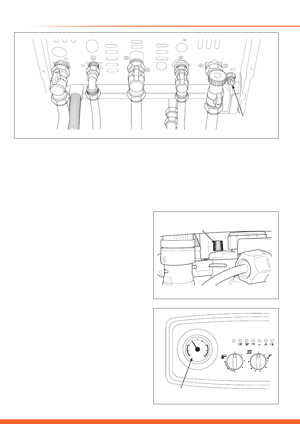
1. Ensure that two manual feed valves and boiler isolation
valves are open, see diagram 11.1.
2. Release the cover cap of the boilers automatic air vent
situated on top of the pump, see diagram 11.2.
The manual feed valves must be closed and the filling
loop disconnected once the pressure sensor, sited on the
boilers control panel, indicates a system pressure
between 1.0 and 1.5 bar, see diagram 11.3.
3. Check that all the water connections throughout the
system are sound and bleed each of the heating systems
radiators in turn. As air is vented the system pressure
may need topping back up to 1.0bar.
Air must be vented from the boiler’s pump by unscrewing
the pumps integral vent plug and allowing water to bleed
for a few seconds. Take care not to allow water to splash
onto any electrical components.
4. When the system is bled of any air it must be filled until
the pressure display indicates a system pressure of 1.5
bar.
5. If the pressure exceeds 1.5 bar discharge the excess
pressure from the system via a radiator valve or pipe
connection. Do not use the safety discharge valve
as the valve seat may become contaminated with debris
and fail to re-seal.
14571
14480
14481
Diagram 11.1
Diagram 11.2
Diagram 11.3
1
2
3
4
bar
0
ON
30
40
50
60
70
80
bar
PUMP
VENT PLUG
AUTOMATIC AIR
VENT COVER CAP
SYSTEM
PRESSURE 1.5 bar
ISOLATION VALVES SHOWN OPEN
IMPORTANT NOTE: In order to maintain the appliances
warranty; after initial filling the heating system must be
thoroughly flushed using a propriety cleanser to remove
foreign material and contaminants.