Glow-worm Betacom C User Manual
Page 45
45
To set the Minimum Setting:
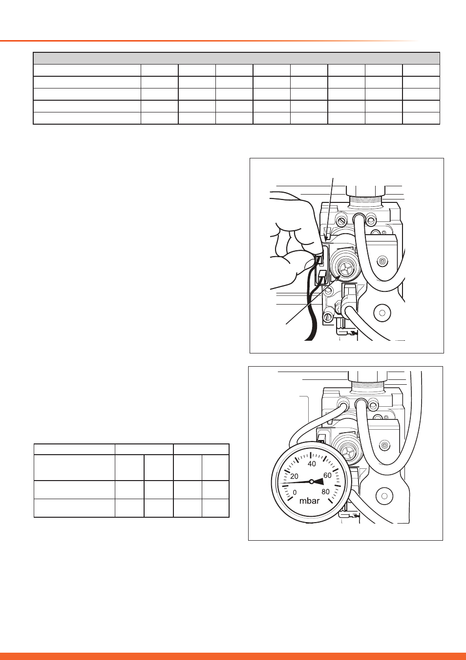
Remove one lead from the gas valve modulating coil, see
diagram 11.17.
Turn boiler’s function switch to the ‘winter’ position (both CH
and DHW).
Turn the Central Heating temperature control knob to the
maximum position.
Connect a suitable pressure gauge to the pressure outlet
on the gas valve, see diagram 11.18.
Remove the protective cover from the gas valve.
Turn inner adjuster with a flat blade screwdriver.
Turn Clockwise: to increase burner pressure.
Turn Counter-Clockwise: to decrease burner pressure.
After adjustment, connect electrical lead and protective
cover.
To set the Maximum Setting:
Connect a suitable pressure gauge to the burner pressure
test point on the gas valve.
Remove the protective cover from the gas valve adjuster.
Connect a suitable pressure gauge to the pressure outlet of
the gas valve.
Turn boiler’s function switch to the ‘winter’ position.
Turn the Central Heating temperature control knob to the
maximum position.
Push the ball inside gas valve modulating coil using a sharp
pointed tool.
Turn outer nut with a 10mm spanner keeping the tool pushed
in:
Turn Clockwise: to increase burner pressure.
Turn Counter-Clockwise: to decrease burner pressure.
After adjustment, connect electrical lead and protective
cover.
11 Commissioning - Nat. Gas (G20) to LPG (G31) Conversion
Betacom 24c
Betacom 30c
NG
(G20)
mbar
LPG
(G31)
mbar
NG
(G20)
mbar
LPG
(G31)
mbar
Burner operating
pressure (minimum)
2.5
8.0
2.3
6.0
Burner operating
pressure (maximum)
12.5
36.5
14
36.0
Factory settings for DIP switches
DS1
DS2
DS3
DS4
DS5
DS6
DS7
DS8
Betacom 24c NG
OFF
OFF
OFF
OFF
OFF
OFF
OFF
OFF
Betacom 24c LPG
OFF
OFF
OFF
OFF
OFF
OFF
ON
OFF
Betacom 30c NG
OFF
OFF
OFF
OFF
OFF
OFF
OFF
ON
Betacom 30c LPG
OFF
OFF
OFF
OFF
OFF
OFF
ON
ON
Diagram 11.18
15525
Diagram 11.17
15524
MODULATING
COIL
GAS VALVE
ADJUSTER
Dip switch 7 must be in the ON position for LPG and OFF for NG.
Dip switch 8 must be in the OFF position for Betacom 24c and ON for Betacom 30c.