5 water system - heating, 14 5.1 general, 2 safety valve – Glow-worm Betacom C User Manual
Page 14: 3 expansion vessel, 4 flow rate, 5 water treatment, 6 general, 7 bypass, 8 filling the sealed system, 9 draining points
14
5.1 General
The boiler is designed to operate on fully pumped,
pressurised sealed systems operating at a maximum of 3bar
pressure and maximum design flow temperature of 85°C.
5.2 Safety Valve
The safety valve is an integral part of the boiler and it cannot
be adjusted.The pipe from the safety discharge valve must
not discharge above an entrance, window or any type of
public access area.
5.3 Expansion Vessel
The boiler’s integral expansion vessel with a capacity of 7
litres (1.5 gallons), is pre-charged to a pressure of 0.5bar
and will accommodate a system volume of 125 litres at an
average water temperature of 75°C and maximum system
pressure of 3 bar.
NOTE: The expansion vessel volume
depends on the total water system volume and the initial
system design pressure.
In GB, Guidance on vessel sizing is
also given in the current issue of BS5449 and BS7074 Part 1.
In IE, current edition of I.S.813 “Domestic Gas Installations”.
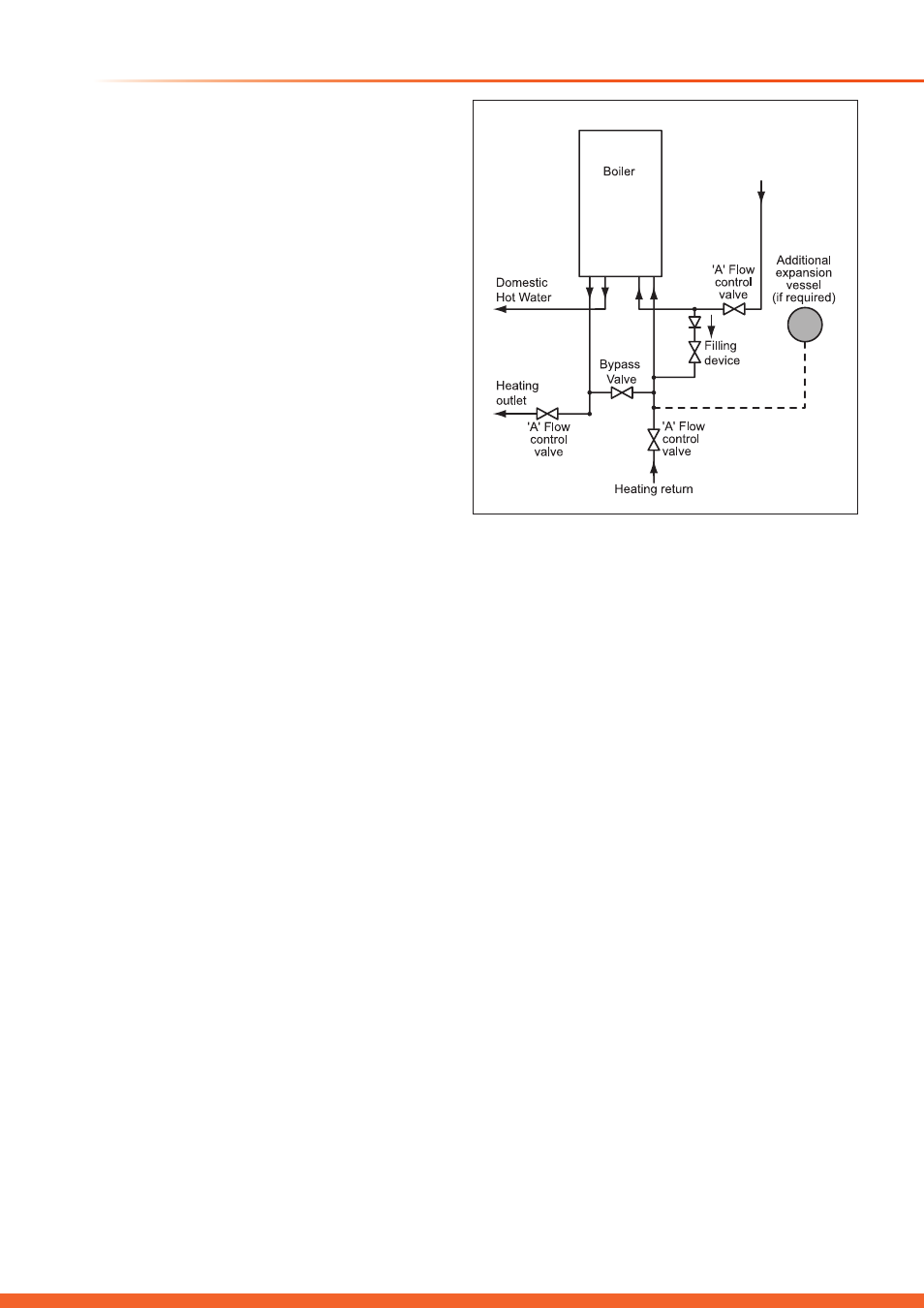
If the system volume is more than 125 litres. an additional
expansion vessel must be fitted to suit the size of the system.
A typical installation of an additional pressure vessel is shown
in diagram 5.1.
5.4 Flow Rate
If it is necessary to alter the flow rate, the system can be
fitted with a lockable balancing valve in the main flow or
return pipes shown as valve “A” in diagram 5.1. The flow rate
through the boiler must not be allowed to fall below that given
in Boiler Specification Table.
The heating circuit should be designed and balanced to give a
20°C temperature rise across the boiler flow and return.
5.5 Water Treatment
Existing system- It is ESSENTIAL that prior to installing the
new boiler the system is thoroughly flushed.
New system- For optimum performance after installation, the
boiler and its associated central heating system should also
be flushed.
Flushing should be carried out in accordance with BS7593:
2006 using a cleanser such as Sentinel X300 or X400, Fernox
Restorer or Salamander corrosion guard cleaner.
IMPORTANT: Ensure all cleanser is removed from the whole
system before adding an inhibitor.
Although the boiler is designed to inhibit the formation of
scale, in hard water areas above 200mg/l, a proprietary scale
reducer should be fitted in the cold water supply to the boiler.
Failure to comply with this requirement may invalidate your
guarantee. Refer to the current issue of BS 5449 and BS
7593 on the use of inhibitors in central heating systems.
5 Water System - Heating
5.6 General
On installation it is important to ensure that the heat
exchanger is not a natural collecting point for air and where
possible, the system pipe work should have a gradient to
ensure any excess air is carried naturally to other purpose
made, air release points.
In high water volume systems or under floor heating systems
where prolonged operation of the boiler is expected at
temperatures below 60
0
C, a by-pass must be installed on the
boiler outlet in order to prevent condensation forming inside
the boiler body. Failure to comply with this requirement will
invalidate the manufacturer’s guarantee.
5.7 Bypass
The system’s water must always be allowed to circulate
whenever the circulation pump is running. A return by-pass
must be provided.
NOTE: It is no longer permissible to use non-thermostatic
radiator valves to allow by-pass through a radiator.
Diagram 5.2 shows the pump head remaining for the heating
system depending on the bypass setting and the speed
setting of the pump, see section 12 Commissioning.
Ensure that under no circumstances does the flow rate drop
below the figure specified, refer to Boiler Specification Table.
5.8 Filling the Sealed System
With water via the filling loop, see diagram 5.3, (the filling loop
is not supplied with the boiler).
5.9 Draining Points
Draining taps must be provided at all low points of the system,
which will allow the entire system to be drained.
Draining taps shall be to the current issue of BS2879.
Diagram 5.1
14561