1 system connection, 2 safety discharge pipe, 3 boiler hanging – Glow-worm Betacom C User Manual
Page 18
18
Diagram 7.2
ISOLATION VALVES SHOWN CLOSED
14348
14347
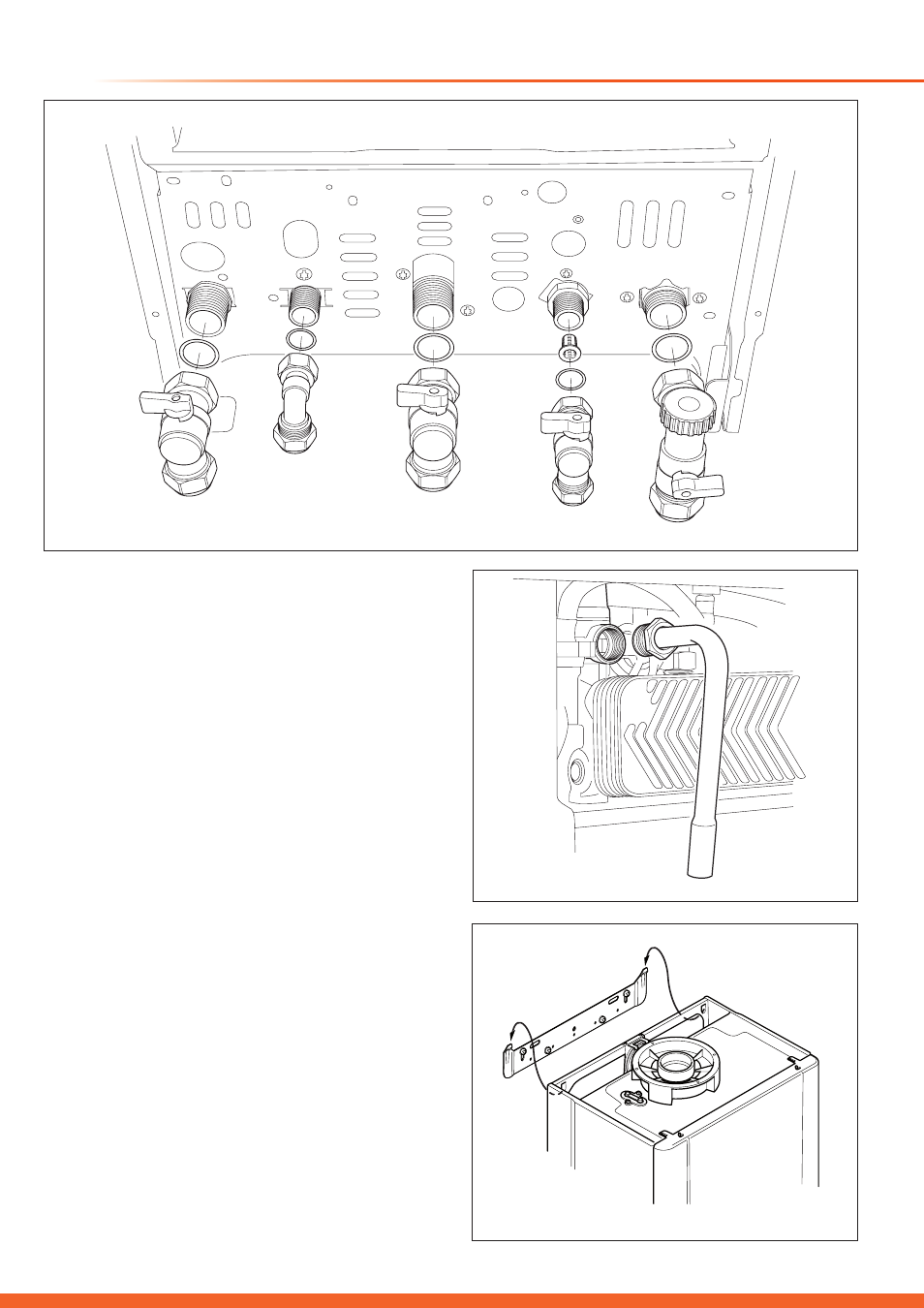
7 Boiler fixing, Gas / Water / Safety Discharge Connections
7.1 System connection
Connect the isolation valves including sealing washers and
cold water inlet filter to the boiler ensuring the washers are
fitted correctly, see diagram 7.1.
Make sure the isolation valves are closed.
7.2 Safety Discharge Pipe
Connect the safety discharge pipe, see diagram 7.2.
This must be extended, using not less than 15mm o.d. pipe,
to discharge, in a visible position, outside the building, facing
downwards, preferably over a drain.
To ease future servicing it is advisable to use a compression
type fitting to extend the safety discharge valve tube.
The pipe must have a continuous fall and be routed to a
position so that any discharge of water, possibly boiling,
or steam cannot create any danger to persons, damage to
property or external electrical components and wiring.
7.3 Boiler Hanging
Lifting the boiler into position, lean the top of the boiler slightly
to the wall and position just above the hanging bracket. Lower
the boiler slowly onto the hanging bracket making sure the
boiler is located in the boiler mounting slots, see diagram 7.3.
IMPORTANT: With regards to the Manual Handling
Operations, 1992 Regulations, the following lift operation
exceeds the recommended weight for a one man lift, refer to
section 17 Manual Handling.
Diagram 7.3
14346
Diagram 7.1
VIEWED FROM THE
REAR OF THE BOILER