14 replacement of parts, 1 general, 1 draining of boiler – Glow-worm Betacom C User Manual
Page 56: 2 draining of boiler hot water circuit, 3 domestic hot water sensor, 4 central heating sensor, 5 fan unit
56
14 Replacement of parts
14.1 General
Replacement of parts must be carried out by a
competent
person.
Before replacing any parts the boiler should be isolated from
the mains electric supply and the gas should be turned off at
the gas service isolation valve on the boiler.
The boiler is cold.
Ensure that components with electrical connections are
disconnected before removal.
Unless stated otherwise parts are replaced in the reverse
order to removal.
After replacing any parts always test for gas tightness and if
necessary carry out functional test of the controls.
For replacement of parts the front casing of the boiler will
need to be removed. To remove undo the two screws on the
underside of the front casing and lift off the retaining lugs, see
diagram 10.1.
The side panels can be removed to aid replacement of parts,
see diagram 12.3.
To hinge a side panel undo and remove the two screws
securing each side panel to the boiler.
14.1 Draining of Boiler
To prevent the need to drain the entire heating system when
replacing the boiler’s integral pump, expansion vessel, safety
relief valve and pressure sensor, the boiler’s hydraulic circuit
may be isolated from the central heating circuit by closing the
boilers isolation valves. Opening the discharge safety valve
will then drain the boiler’s hydraulic circuit.
NOTE: clean the valve seat to ensure it seals before re-filling
the boiler.
After replacing parts open the heating flow and return isolating
valves and refill, vent and pressurise the heating circuit, refer
to section 11.2.
Check for leaks.
14.2 Draining of Boiler Hot Water Circuit
Drain the Domestic Hot Water circuit by closing the cold-water
isolation valve on the boiler.
Open one or more hot water taps to drain the hot water circuit.
After replacing parts open the cold-water isolation valve and
slowly open a hot water tap to remove air. Close the hot water
tap and check for any leaks.
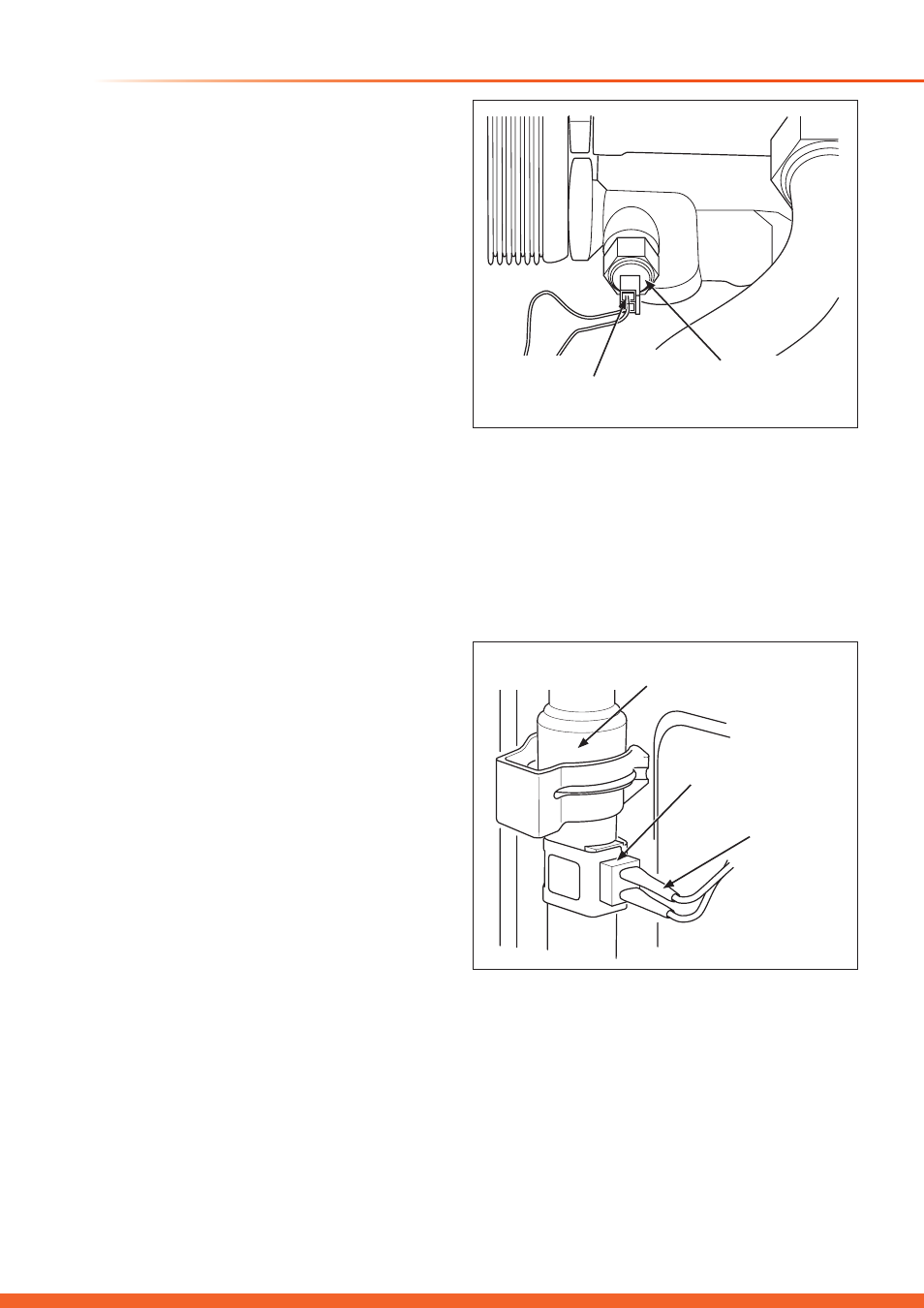
14.3 Domestic hot water sensor
For access, refer to section 14.1.
The domestic hot water sensor is located on the left side of
the hydroblock’s hot water side, see diagram 14.1.
Carefully disconnect the electrical connections from the
domestic hot water sensor.
Remove the domestic hot water sensor using a 13mm
spanner.
Fit the replacement domestic hot water sensor ensuring the
washer is correctly fitted.
Re-fit the electrical connections to the replacement sensor.
14575
14576
Diagram 14.1
Diagram 14.2
14.4 Central heating sensor
For access, refer to section 14.1.
The C.H. sensor is located on left side of the combustion
chamber on the outlet of the primary heat exchanger, see
diagram 14.2.
Unclip the C.H. sensor from the pipe.
Disconnect the electrical connections from the C.H. sensor.
Fit replacement C.H. sensor.
Re-fit the electrical connections.
ELECTRICAL
CONNECTIONS
ELECTRICAL
CONNECTIONS
DOMESTIC HOT
WATER SENSOR
CENTRAL HEATING
SENSOR
PRIMARY HEAT EXCHANGER
OUTLET PIPE
14.5 fan unit
For access, refer to section 14.1.
Refer to section 12.2 to replace the fan.
Fit the replacement fan unit in reverse order and reconnect
the electrical connections and sensing tube.