Pull-up resistors for communications lines, The parallel communications interface, Parallel communications interface – Echelon FTXL Hardware User Manual
Page 29
FTXL Hardware Guide
21
Pull-Up Resistors for Communications Lines
For the parallel communications interface, you must add 10 kΩ pull-up resistors
to all communication lines between the FPGA device and the FTXL Transceiver
Chip (the IO0-IO10 pins of the FTXL Transceiver). These pull-up resistors
prevent invalid transactions on start-up and reset of the FPGA device or the
FTXL Transceiver Chip. Certain I/O pins can revert to a floating state without a
pull-up resistor, which can cause unpredictable results.
The Parallel Communications Interface
An FT 3120 Smart Transceiver can connect to application-specific external
hardware through 11 pins, named IO0-IO10. The Smart Transceiver design
allows these pins to be configured as an
I/O object
that provides programmable
access to an I/O driver for a specified on-chip I/O hardware configuration and a
specified input or output waveform definition.
The FTXL 3190 Smart Transceiver Chip is an FT 3120 Smart Transceiver with a
firmware image that is configured to use the IO0-IO10 pins as a
parallel I/O
object
, which defines a bidirectional, half-duplex, 8-bit data port and a 3-bit
control port for connecting to the FPGA device. Because the FTXL Transceiver
communicates with an external host processor, the FPGA device, the parallel I/O
interface is configured in the Smart Transceiver’s slave B mode.
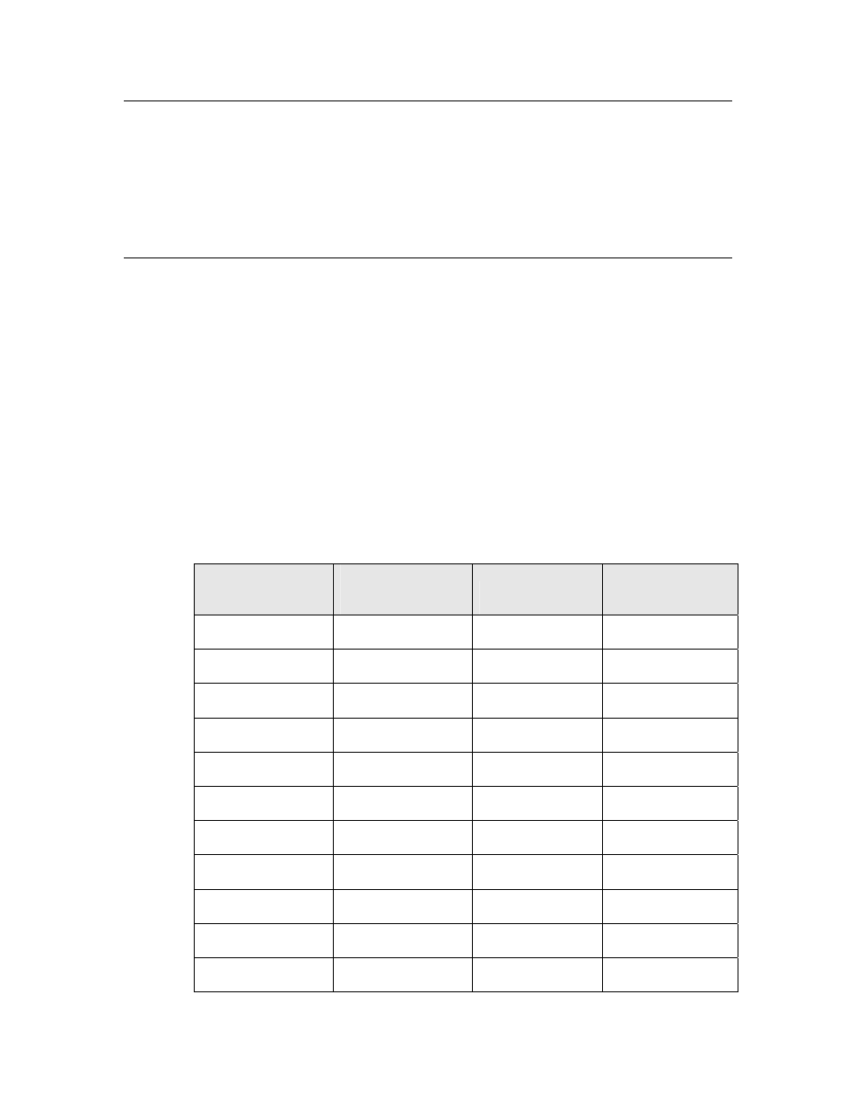
Table 10 summarizes the pin assignments for the FTXL Transceiver, and Figure
7 on page 23 shows the parallel interface for the FTXL Transceiver.
Table 10. FTXL Transceiver Pin Assignments for the Parallel Interface
FTXL Transceiver
Pin Number
FTXL Transceiver
Pin Name
Signal Name
Direction
4 IO0
D0/HS
Input
and
output
3 IO1
D1
Input
and
output
2 IO2
D2
Input
and
output
43 IO3
D3
Input
and
output
42 IO4
D4
Input
and
output
36 IO5
D5
Input
and
output
35 IO6
D6
Input
and
output
32 IO7
D7
Input
and
output
31 IO8
CS~
Input
30 IO9
R/W~
Input
27 IO10
A0
Input