The ftxl adapter board, Jumper settings, Connectors and headers – Echelon FTXL Hardware User Manual
Page 21
FTXL Hardware Guide
13
The FTXL Adapter Board
The primary function of the FTXL Adapter Board is to provide the 5 V power to
the FTXL Transceiver Board from the 3.3 V power of the DBC2C20 development
board. The FTXL Adapter Board also provides access to all of the FTXL
Transceiver I/O lines through headers on the board.
Connect the FTXL Adapter Board to the DBC2C20 development board by joining
the FTXL Adapter Board’s J7 and J5 connectors to the DBC2C20 development
board’s P22 and P23 headers.
Jumper Settings
The FTXL Adapter Board includes two sets of jumpers (J4 and J9). However, the
FTXL Developer’s Kit uses only the J9 jumper, as described in Table 6.
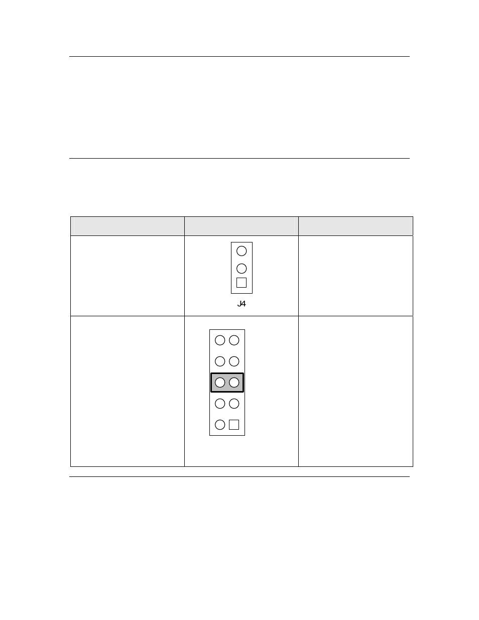
Table 6. FTXL Adapter Board Jumper Settings
Function
Jumper
Description
Interface Selector (J4)
This jumper is not used for
the FTXL Developer’s Kit.
Leave this jumper
unmounted.
Chip Select Signal Selector
(J9)
CS1
CS2
CS3
CS4
CS5
J9
This jumper selects which
Chip Select signal to use in
the J2 connector.
You can set this jumper in
any position, but the setting
for the J9 jumper on the
FTXL Adapter Board must
match the jumper setting for
the J7 jumper on the FTXL
Transceiver Board.
The factory shipped default
setting for this jumper is to
mount it across pins 5 and 6,
as shown.
Connectors and Headers
The FTXL Adapter Board includes eight connectors and headers, of which the
FTXL Developer’s Kit uses the ones listed in Table 7 on page 14.
The FTXL Developer’s Kit does not use the J3 or J10 headers.