Mounting your xl 650, Initial set up – Dillon Precision XL 650 User Manual
Page 6
7
2. Mounting your XL 650:
A.
Locate a sturdy bench at least
24” wide and 14” deep, with 44” of
overhead clearance. We suggest a
minimum of 1” plywood or equivalent,
secured to the back wall. The work-
bench should be tall enough to place
your eye level about 18” above the
bench.
Note: It is important that the leading edge
of the bench has an overhang of at
least 3/4”. If the overhang is less
than 3/4”, the crank will interfere
with the front of the bench when the
operating handle is lowered. Unless
you have Strong Mounts, then none
of this is necessary.
B. Tools Needed:
You will need the following to mount and
set up your machine:
1. Electric drill
2. 17/64” drill bit preferred, 1/4” – 9/32” OK
3. Mounting Hardware Kit (#14355) or
four 1/4” through bolts with nuts and
washers
Note: The bolts should be at least 1 1/2”
longer than the thickness of the
mounting surface.
4. Two 7/16” wrenches if using kit
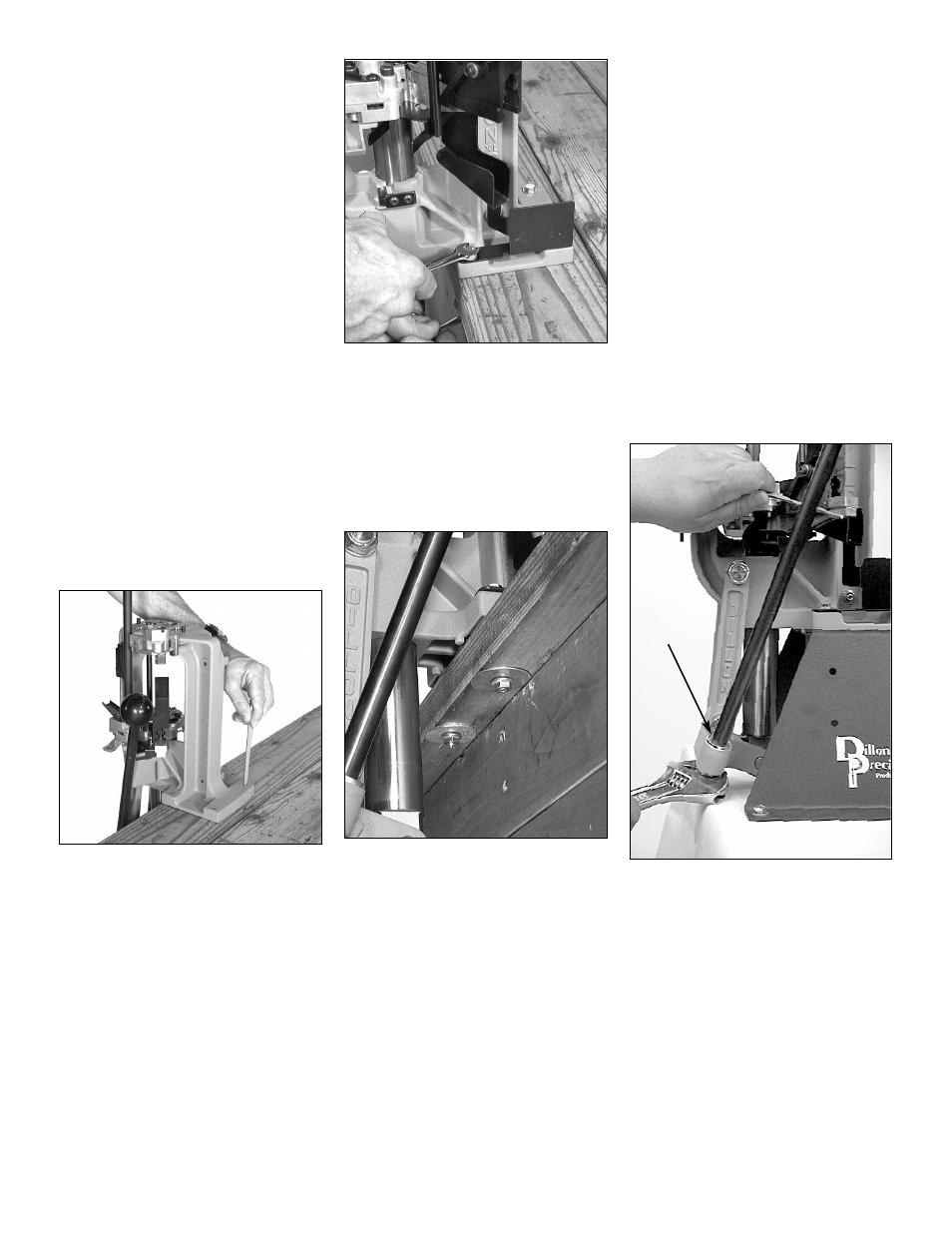
FIG 1
C. Drill the mounting holes FIG 1:
1. Using the machine as a template, mark
the four holes.
2. Using a 1/4” bit, drill the holes.
FIG 2
D. Bolting the machine to the
bench FIG 2:
Note: If you do not have a Mounting Hard-
ware Kit, ensure that you use 1/4”
or equivalent through bolts (with
large area washers if mounting to
wood). Do not use lag bolts or wood
screws!
FIG 3
1. Mount the left side of the machine with
the small washers on top and the large
washers on the bottom FIG 3. Run
the two left side nuts down finger tight.
2. Place the chute/bin bracket FIG 2 on
the right side of the machine. As
before, place the small washer on top
and the large washers on the bottom
and thread the nuts.
Note: The chute/bin mount goes under
the two right hand mounting bolts so
it must be installed as you are
mounting the machine FIG 2.
Check the fit of the chute/bin
mount. The chute/bin mount
should rest snugly against the
frame. Also, make sure that the
walls of the chute are parallel and
have not been bent during ship-
ping or installation.
3. Using two 7/16” wrenches, tighten all
four bolts down.
3. Initial Set Up
If you ordered your XL 650 for a specific
caliber, it comes factory adjusted for that
caliber (minus dies) with the appropriate
“caliber specific” parts included. In fact, a
Dillon technician runs casings and primers
through the machine to check its function.
Note: As you assemble your machine,
we recommend that you cross
check caliber specific parts, includ-
ed with your machine, with those
specified in the caliber conversion
chart (pages 42-44). The
point being – if we sent you the
wrong part, you’ll want to know it
before getting started. Reference
page 35 for instructions on how to
use the caliber conversion chart.
FIG 4
A. Installation of the handle FIG 4:
1. Hold the washer (see arrow FIG 4)
over the hole on the right side of the
crank and insert the handle.
2. Place a 5/32” Allen wrench or screw
driver through the hole in the handle to
help your grip.
3. Tighten the nut using a 7/8” wrench.