Dillon Precision XL 650 User Manual
Page 25
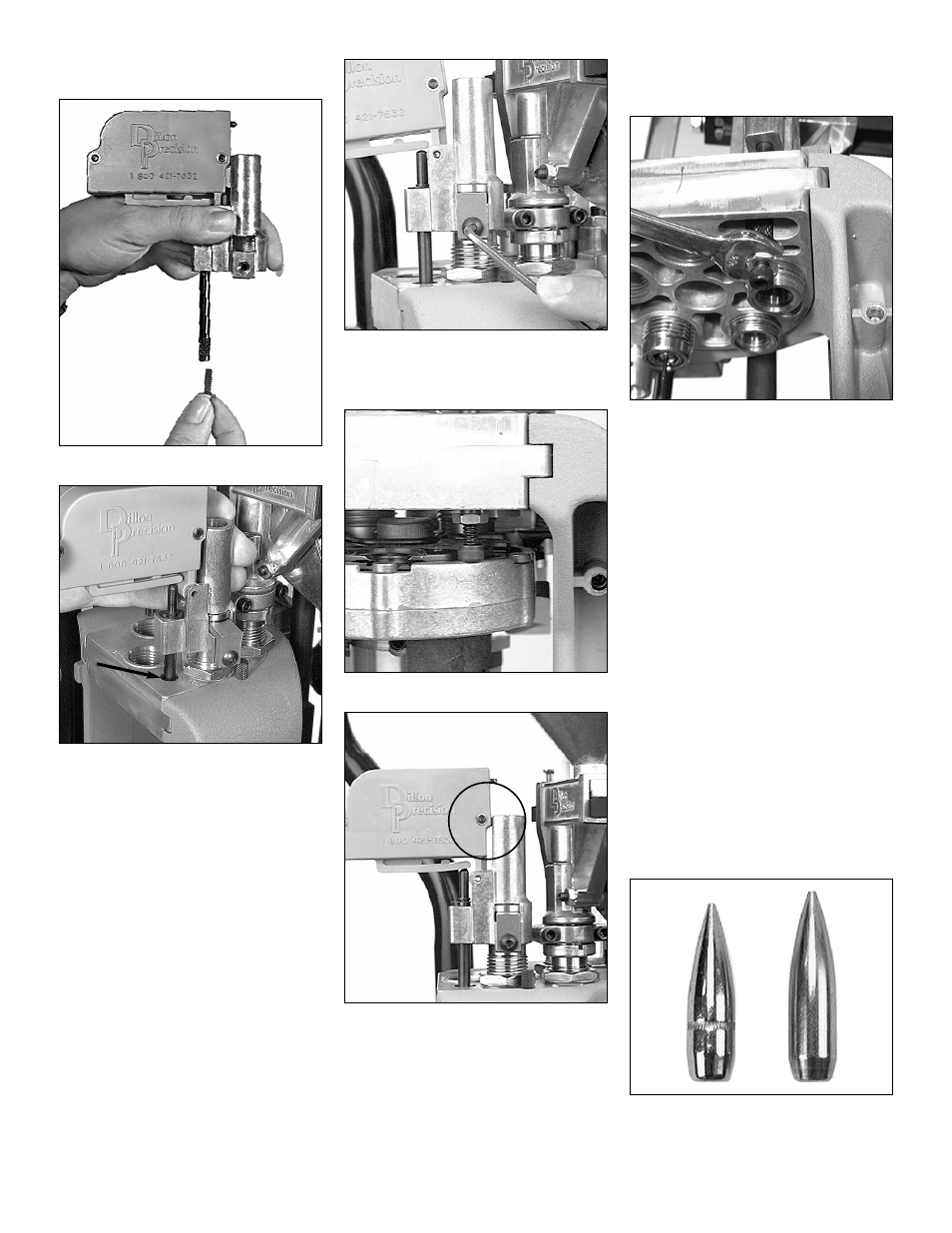
3. Run the lockring down. Using a 1-
1/8” wrench snug the lockring.
FIG 107
FIG 108
4. Remove the 10-24 screw and nut
from the black push rod FIG 107 and
place the powder check system on
the powder check die FIG 108.
Center the black push rod (see arrow
FIG 108) in the hole that is to the left
of the die.
FIG 109
5. Reinstall and snug the die clamp
screw FIG 109.
FIG 110
FIG 111
6. FIG 110 Screw the 10-24 screw and
nut fully into the rod. Raise the plat-
form. Unscrew the 10-24 screw
until it contacts the edge of the plat-
form FIG 110. Lower the platform
part way and unscrew the screw
(counter-clockwise) until raising the
platform causes the buzzer housing
to rock into the side of the die collar
FIG 111.
FIG 112
7. Secure the jam nut by holding the
black push rod while tightening it
using a 3/8” wrench FIG 112.
Note: Once you’ve adjusted the powder
bar for the desired powder charge –
installation and adjustment of the
powder check system can be com-
pleted.
J. Station 4 – How to deter-
mine the proper seating
depth:
Before installing and adjusting the seating
die you’ll need to know how to determine
the proper seating depth. How far the bullet
is seated into the case will determine the
overall length (OAL). Several factors go into
determining the proper OAL – such as, the
maximum recommended OAL, listed in the
reloading manual, and the type of bullet
being loaded. The type of bullet can deter-
mine the OAL by one of two ways. If the
bullet has what is called a cannelure, FIG
113, this will determine the proper OAL.
FIG 113
26