Dillon Precision XL 650 User Manual
Page 40
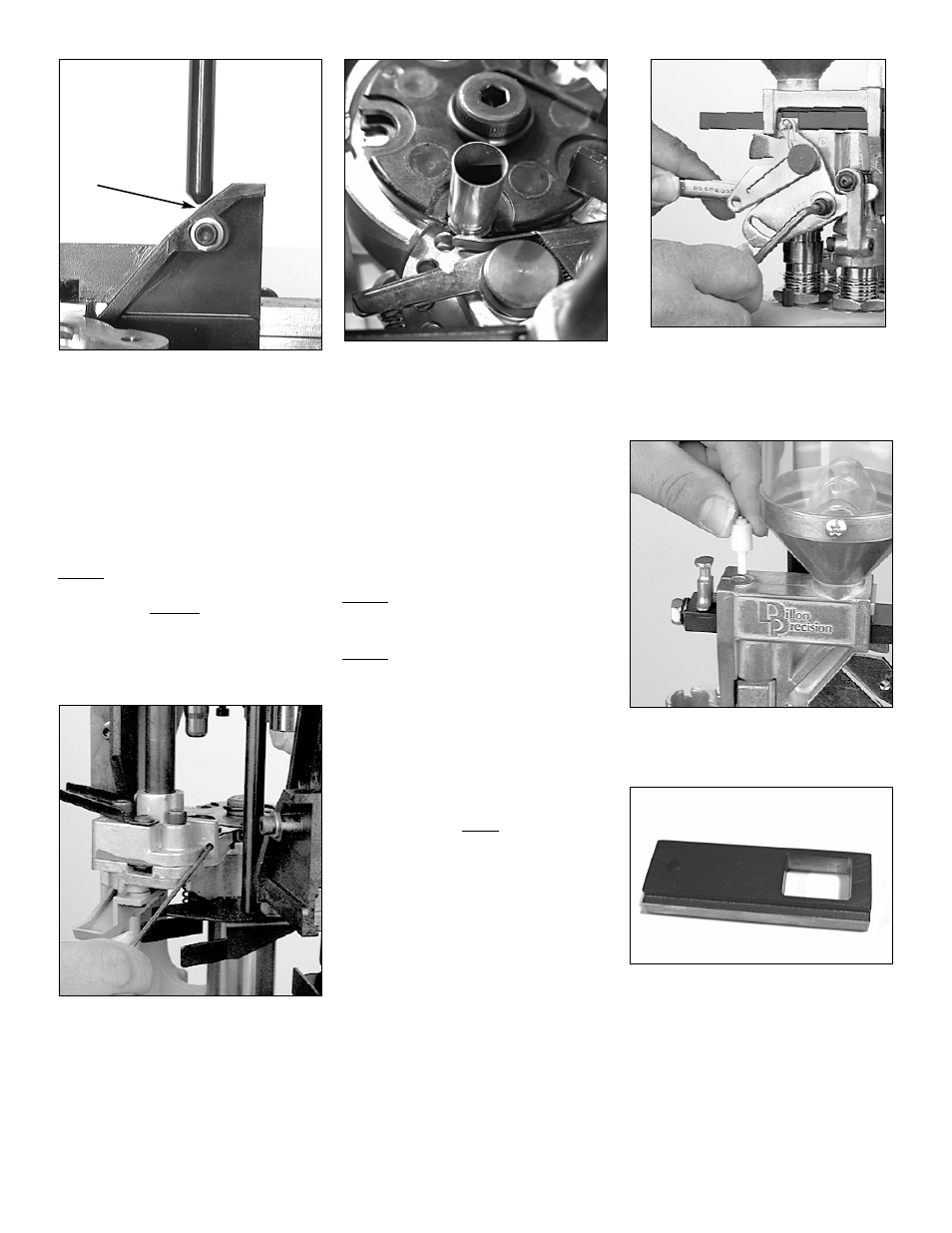
FIG 193
Note: The objective here is that – at the
point the case becomes fully insert-
ed into shellplate (with the handle
against its full aft stop) – the cam-
ming pin is still in contact with the
case insert slide cam – or at least
within a 1/16” of the case insert
slide cam (see arrow FIG 193).
5. Once properly adjusted, tighten the
lock nut.
Step 17) Adjusting the Station 2
Locator Tab (see note just
above Step 16):
The adjustment of the Station 2 locator
tab is best accomplished with the toolhead
removed.
1. Place a case in Station 2.
FIG 194
2. Using a 5/64” Allen wrench, insert it
into the side of the primer feed body
FIG 194. Turn the screw to adjust the
locator tab. A turn clockwise will
move the tab back away from the
shellplate and a turn counter clock-
wise will adjust it closer to the
shellplate.
FIG 195
3. Adjust the locator tab so that the tab
just clears the case FIG 195. The
objective here is, with the case fully
inserted into the shellplate, the loca-
tor tab should not come into contact
with the case. However, the tab
should be close enough so as to not
allow the case to lose its position in
the shellplate. The distance between
the locator tab and the case should
be about .010” or about the thickness
of a business card.
Step 18) Refer to the Rifle Section or
Pistol Section to set up the tool
head.
Step 19) Station 2 – Changing out the
powder bar:
Refer to “About Powder Bars” under the
Rifle or Pistol Section or refer to the Caliber
Conversion Chart (pages 46-48) to deter-
mine whether or not you’ll need to change
the powder bar.
To change the powder bar:
1. Remove the powder from the powder
measure (ref. Step 2).
2. Hold the powder measure over a
powder container and cycle the
powder bar with your thumb to
empty all remaining powder.
FIG 196
3. Using a 5/32” Allen wrench, loosen
the bellcrank screw just enough to
remove the white cube from the side
of the powder bar FIG 196.
FIG 197
4. Remove the white plastic retaining
plug. (FIG 197)
FIG 198
5. a) If the large powder bar is current-
ly installed – remove the large pow-
der bar.
b) If the small powder bar is currently
installed – remove both the small
powder bar and small powder bar
spacer FIG 198. Note: The purpose of
the spacer is simply to make up for
the room allowed for the large pow-
der bar.
41