Dillon Precision XL 650 User Manual
Page 14
15
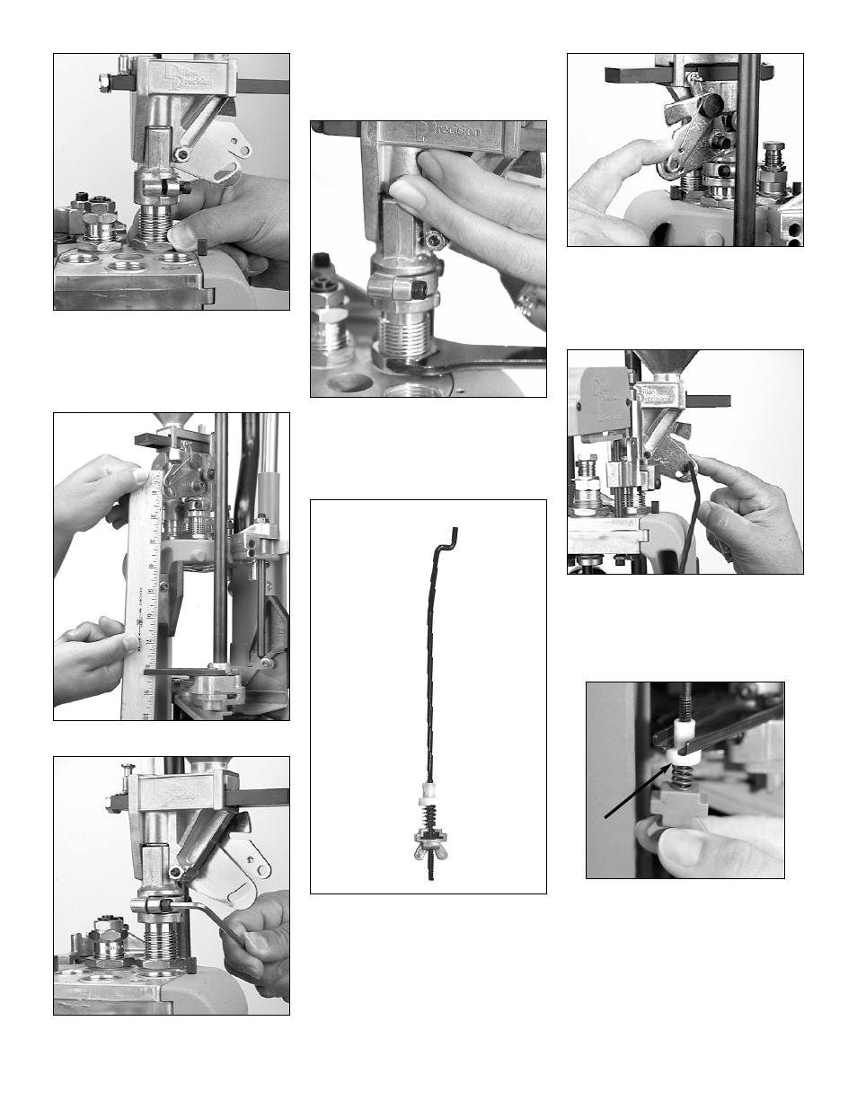
FIG 44
6. Once you’ve achieved the desired
amount of bell – with the case in
Station 2, raise the platform. Run the
lockring down hand tight FIG 44.
FIG 45
FIG 46
7. Insure the bellcrank and the failsafe
bracket FIG 45 are aligned. Using a
5/32” Allen wrench, snug the collar
clamp screws FIG 46.
FIG 47
8. While holding the powder mea-
sure, snug the lockring using a 1
1/8 wrench FIG 47. Now lower the
platform.
FIG 48
F. Station 2 – Installation of
the failsafe rod assembly
FIG 48:
The purpose of the powder measure fail-
safe rod is to return the powder bar to its re-
charge position.
FIG 49
1. Using your forefinger, move the lock-
link (#17838) down to align the hole
with the slot on the Powder Measure
bellcrank (#97034) FIG 49.
FIG 50
2. Insert the rod (#13629) through the
holes FIG 50.
3. Loosen the blue plastic wing nut
(#13799).
FIG 51
4. Slide the failsafe rod into the failsafe
return bracket. Push the shoulder
washer up into place (arrow FIG 51)
and tighten the blue plastic wing nut
until the end of the threaded rod is
even with the wings of the wing nut.
Note: Do not fill the powder measure or
adjust the powder bar until the rest
of the dies are installed and adjusted.