Dillon Precision XL 650 User Manual
Page 20
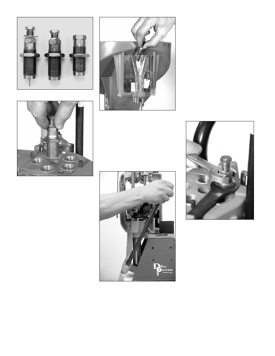
FIG 78
FIG 79
C. Station 1 – Installation
and adjustment of the siz-
ing/decapping die FIG 78:
Warning: Never attempt to de-prime a live
primer, an explosion may result
causing serious injury or even
death.
Note: Whenever sizing a bottle-necked
case you must lubricate the case
first, otherwise you will stick the
case inside the sizing die. For
more information refer to the section
“Lubricating Your Brass” (page 11).
1. Raise the platform, by lowering the
handle all the way.
2. Install the sizing die by screwing it
into Station 1 FIG 79. Continue to
screw the die down until the mouth
of the die is about the thickness of a
dime away from the shellplate. Lower
the platform by raising the handle to
its upright position.
FIG 80
3. Drop a lubricated case into the case-
feed funnel FIG 80. Here the case
drops to the casefeed arm bushing.
4. Raise the platform. The inserter cam
pushes the feed arm bushing over the
body, dropping the case onto the
Station 1 locator.
5. Lower the platform. The case is
inserted into Station 1.
FIG 81
Note: After raising the handle, insure that
you push the handle against its full
aft stop FIG 81. This will insure
that the case is fully inserted into
Station 1.
Note: When priming, pushing the handle
against its full aft stop will insure
that the primer is fully seated.
6. Again raise the platform. The case is
now sized. If the case has a spent
primer, it will be deprimed. Notice
the resistance at the end of the
downstroke. This is the resistance of
the case in the sizing die. Lower the
platform. The case will index to
Station 2.
7. Remove the case from Station 2 and
place it in the case gage. From this
point – follow the instructions provid-
ed under “Rifle Section B. Station 1 –
How to use the Case Gage.”
8. Once the sizing die is properly
adjusted, replace the case into Station
1 and raise the platform. Leave the
platform in the raised position with
the case fully inserted in the die. This
will ensure that the die remains in
position when tightening the lockring.
FIG 82
9. Run the lockring down until it con-
tacts the toolhead. Using a 1” wrench
to turn the lockring and a 3/4”
wrench to hold the die body, snug
the lockring FIG 82.
21
Sizing/Decapping Die
Seating Die
Crimp Die