Dillon Precision XL 650 User Manual
Page 31
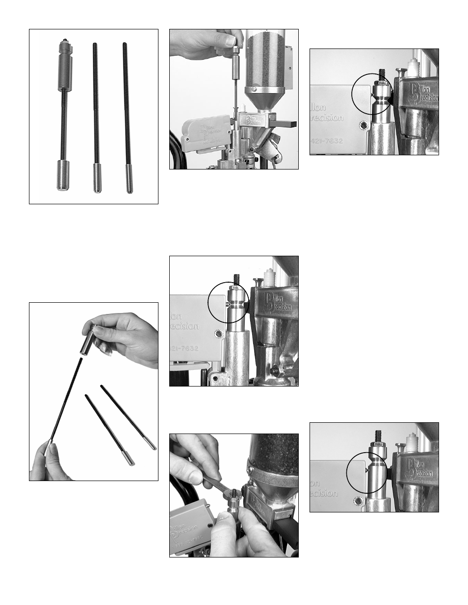
FIG 139
A. Installation and adjustment of
the powder check rods
FIG 139:
1. Remove the powder check rods from
the bag FIG 139. The three rods fit
different calibers. On the left .44-.45
caliber, center .30-.41 caliber and on
the right .22-.29 caliber.
FIG 140
2. Choose the correct rod for the caliber
you’re loading. For example – if
you’re loading .38 Spl. you would
use the .30-.41 caliber rod. If the rod
you’re using doesn’t have the
grooved sleeve on it, remove the
grooved sleeve from the one you’re
not using and thread it onto the cor-
rect rod FIG 140.
FIG 141
3. Insert the rod into the powder check
die FIG 141.
4. Put on your safety glasses.
5. Place a case with the proper powder
charge into Station 3 and raise the
platform. Leave the platform in the
raised position.
FIG 142
6. Thread the grooved sleeve down so
that the contact pin fits inside the
groove as seen in FIG 142.
FIG 143
7. Snug the lock nut with a 3/8” wrench
FIG 143.
FIG 144
B. Powder Check System
Demonstration:
1. Place a primed but empty case (case
with no powder) into Station 3 and
raise the platform. The contact pin is
above the groove FIG 144 (the alarm
sounds) indicating that the case has a
low or no charge.
2. Lower the platform. Remove the
empty case from Station 4 and place
it in Station 2.
3. With the empty case in Station 2 give
it a double charge.
To do so:
a. Raise the platform all the way to
charge the case.
b. Lower the platform halfway (enough
for the powder bar to return to its start-
ing point without indexing the case to
Station 3 and releasing the locklink).
c. Again, raise the platform to give the
case a second charge of powder.
d. Index the case to Station 3 by lower-
ing the platform all the way. (The case
is now double charged and ready to be
checked by the Powder Check System.)
FIG 145
4. Raise the platform FIG 145. The con-
tact pin is below the groove (the
alarm sounds) indicating that the
powder charge is double or more.
32