Placing, 30hh,hj, Carrier – Carrier 30HH User Manual
Page 7: Installation
Attention! The text in this document has been recognized automatically. To view the original document, you can use the "Original mode".
Carrier
INSTALLATION
30HH,HJ
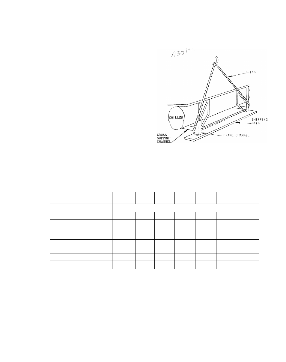
piping or equipment. Move the unit in an upright
position, and let it down gently from the truck
or
rollers.
On
30HH,HJ015-030
units
the
sling
can be placed under the frame channels at the
main support (Fig. 7). On 30HH,HJ045 thru 065
units, the sling can be placed under the skids.
Placing
To anchor the equipment;
1.
Locate the hold down bolts as shown in the
dimension
drawings.
The
areas
where
the
four corners will be located should be ap
proximately level before the unit is placed.
2.
Set the unit in place and level with a spirit
level on the frame channels.
3.
Bolt the unit to the floor. This is usually de
sirable for basement or ground floor instal
lations
that
can
transmit
vibration
to
the
ground
without
affecting
the
building
struc
ture.
Fig. 7 - Rig Sling to Hoist Unit
(015-030 Shown)
Table 2 - Compressor Motor Physical Data
Unit Size
30HH, H]
0J5
30HH, H]
020
30HH, HJ
025
30HH, HJ
030
30HH, HJ
045
30HH
055
30HH, HJ
065
Compressor Type
Hermetic Reciprocating
Number
2
2
2
3
4
4
Sizes
1 - 6D73»
2 - 6D68
1 - 6D68
1 - 6D73*
2 - 6D73*
3 - 6D73*
1 - 6D68
3 - 6D73
4 - 6D73*
Cylinder (Total No.)
6
12
12
12
18
24
24
Speed - 60 Cycle (rpm)
1750
1750
1750
1750
1750
1750
1750
- 50 Cycle (rpm)
1460
1460
1460
1460
1460
1460
1460
Oil Charge (10 pt per compr) (pr)
10
20
20
20
30
40
40
Cylinder Unloading Devices (No.) t
2
1
1
1
1
*6D7 3 Compressors are used on rhe 30HH models
only. 30HJ Models are supplied with 6D75 com
pressors.
t Each cylinder unloading device unloads two cylinders
of the compressor when it is energized.