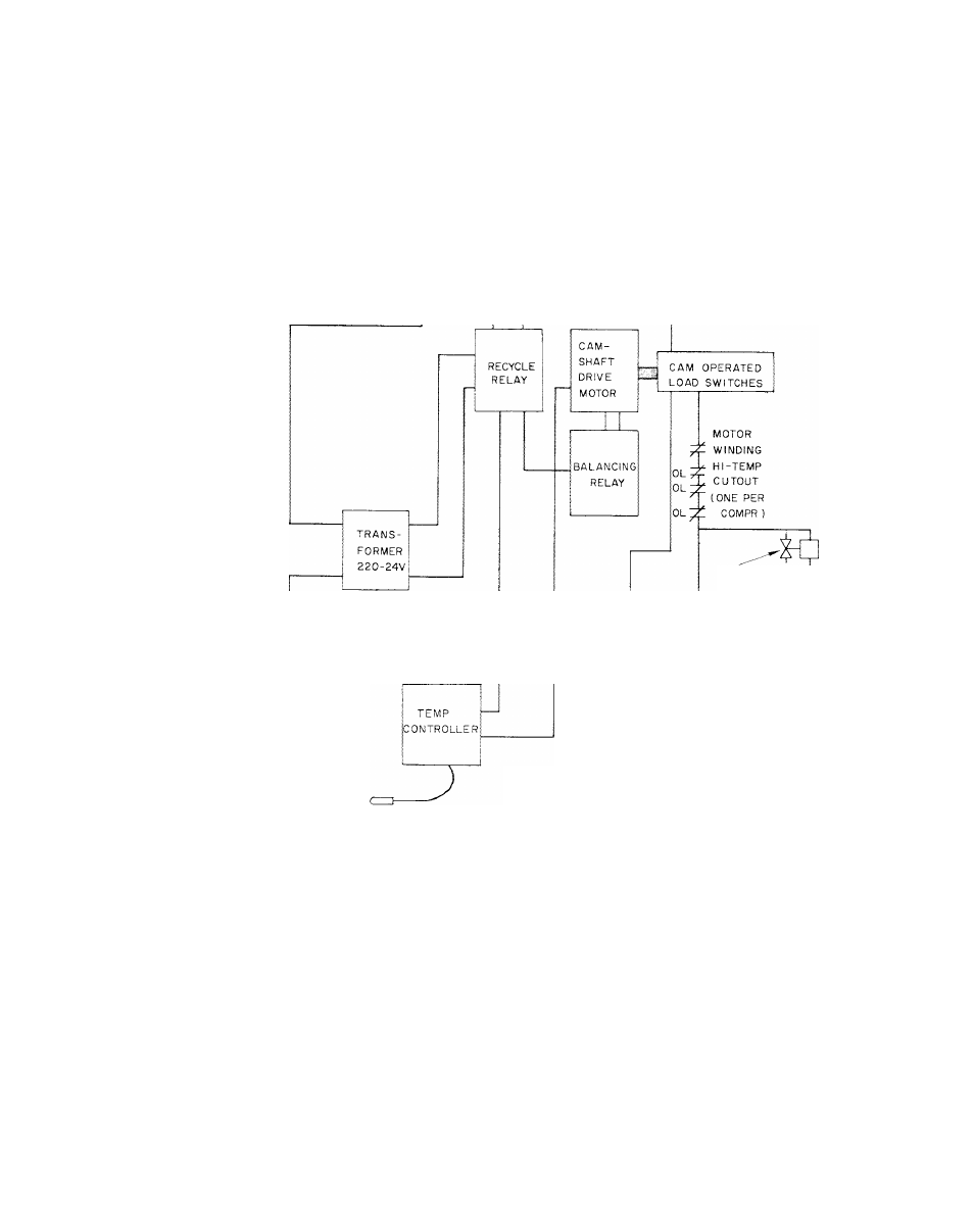
Installation, Fig. 41 - control wiring diagram, Carrier – Carrier 30HH User Manual
Page 42
Attention! The text in this document has been recognized automatically. To view the original document, you can use the "Original mode".
INSTALLATION
Carrier
0FF-0\'
SWITCH
CHILLED WATER
SAFETY THERMOSTAT
-USE
COMTACT
IN COMPR
MOTOR
STARTERS
220 V
COMPR
CRANKCASE
HEATERS
(ONE PER
COMPR )
LOCATION FOR
FIELD-SUPPLIED
AUXILIARY SAFETY
INTERLOCKS
PANEL ViX
light
]^
FUSE
-4]
TEMP CONTROL
BULB IN CHILLED
WATER LINE
SOLENOID
OPERATED
CYLINDER
UNLOADING DEVICE
(SEE NOTE 3)
©
LIQUID LINE
SOLENOID
VALVES
HOLDING COILS
IN COMPR
MOTOR
STARTERS
(SEE NOTE I )
w
LO-HI
PRESSURE
SWITCHES
NOTES:
]. The 30HH,i!J units have the following number of com
pressors:
30HH,HJ015
- i
30HH,KJ020, 025, 030 - 2
30HH,HJ045
- 3
30HH055, 30HH,I!J065 - 4
On
multiple
compressor
units
the
compressors
are
started in sequence from individual load switches.
2. Liquid line solenoid valves are supplied one per refrig
erant circuit on all models.
3. The single compressor 30HH,HJ015 models are supplied
with two cylinder unloading devices.
4. Detailed reproducible wiring diagrams showing control
wiring, power wiring and location of control com.ponents
are available from Carrier offices.
Fig. 41 - Control Wiring Diagram
36