Electrical data, Capacity controls, 30hh,hj – Carrier 30HH User Manual
Page 40: Carrier, Installation
Attention! The text in this document has been recognized automatically. To view the original document, you can use the "Original mode".
30HH,HJ
INSTALLATION
Carrier
ELECTRICAL DATA
The
6D73
and
6D75
compressors
(30HH,HJ
-
015,025,030 models) for 220 volt, 50 cycle ap
plication are supplied with six lead, part wind
ing
motors
and
extra
starters
to
provide
part
winding
start.
This
is
available
for
the
same
60 cycle units on special order.
Time delay relays are required for part winding
starting.
Staggered
starting
of
multiple
compressors
is
insured
by
the
step
controller
camshaft
drive
motor
and
recycle
relay.
Time
delay
relays
are not required.
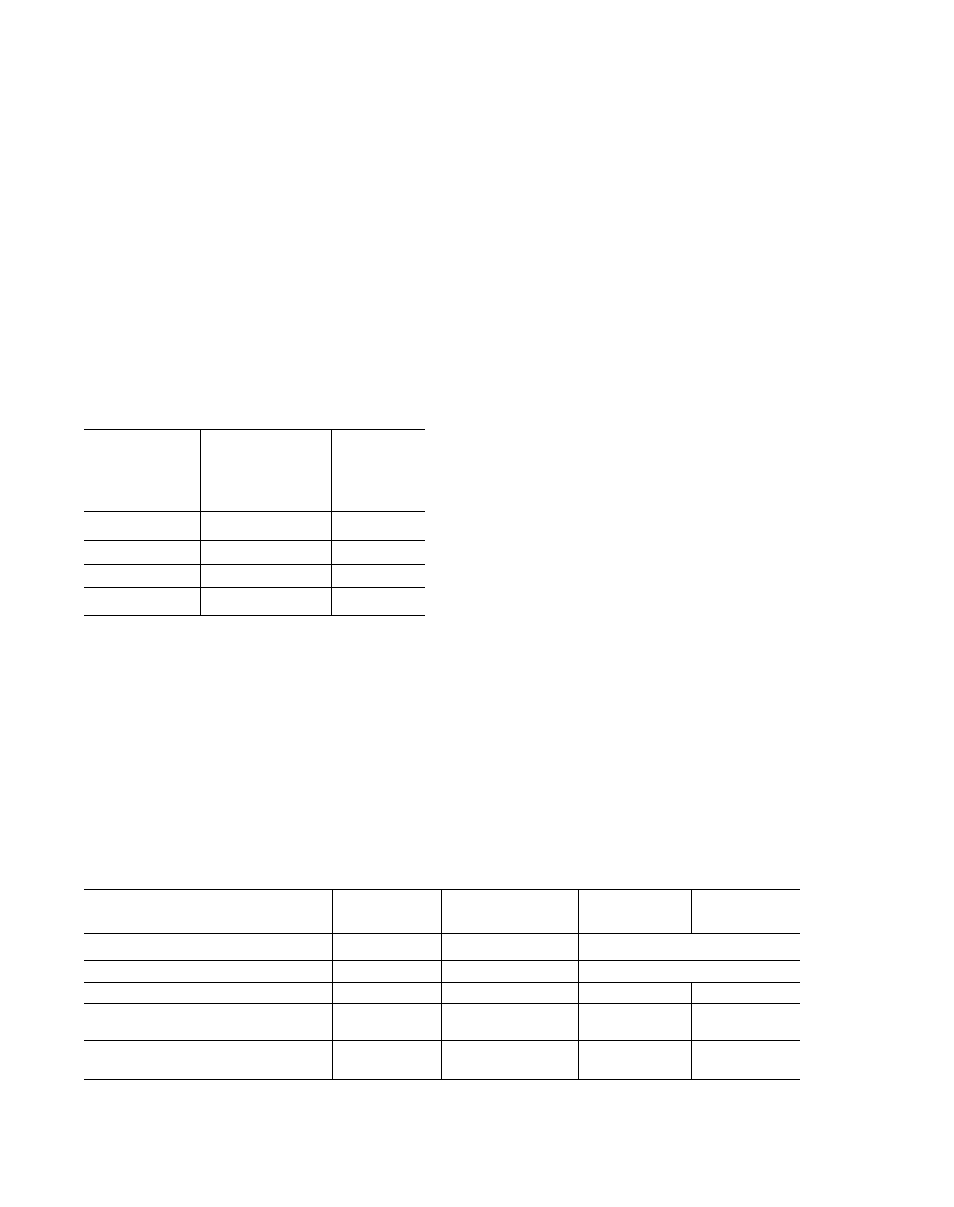
Volts - 3 Phase
60 Cycle
Normal Network
Voltage
Application
Range
Voltage
Limits for
Satisfactory
Operation
208
208
187 to 229
230
220 to 240
198 to 264
460
440 to 480
396 to 528
575
550 to 600
495 to 660
CAPACITY CONTROLS
The
30HH,HJ
units
are
supplied
with
capacity
controls which cycle compressors and load and
unload
cylinders
of
one
compressor
to
give
capacity control steps shown in Table 12 below.
The
capacity
controls
supplied
with
each
unit
consists of a step controller, a solenoid-operated
cylinder
unloading
device
(two
unloaders
on
30HH015 and 30HJ015 units) and a chilled water
temperature controller.
Step Controller - The step controller includes
a small, low voltage motor with clockwise and
counter-clockwise
rotation
windings
that
drive
a
camshaft.
The
factory-set
cams
operate
load
switches
which
start
or
stop
compressors
and
load
or
unload
cylinders.
The
motor
windings
of the camshaft drive motor are energized by
a
balancing
relay
which
contains
windings
in
the
temperature
bridge
circuit
between
the
chilled
water
temperature
controller
and
the
motor
balancing
potentiometer
located
at
the
end of the camshaft. When the unit is loading
or
unloading
(counter-clockwise
or
clockwise
rotation of the camshaft drive motor), one chilled
water
temperature
corresponds
to
one
position
of the camshaft. Camshaft rotation is limited in
each direction by limit switches.
The step controller also includes a recycle re
lay which insures that the camshaft is fully re
cycled to the unload position at startup or after
a
power
interruption.
After
the
camshaft
has
recycled to the unload position, the chilled water
temperature
controller
takes
control
and
starts
camshaft
rotation
in
the
load
direction
which
starts
the
compressors
in
sequence,
insuring
staggered compressor starting in every case.
W'hile the unit is operating, the factory cam set
tings on the step controller protect the compres
sors against rapid cycling.
A
small
transformer
is
provided
in
the
step
controller which supplies 24 volt power to the
camshaft drive motor.
Cylinder Unloading Device - On the 30HH,HJ020
thru 30HH,HJ065 units a single cylinder unload
ing device is installed on the lead compressor.
The lead compressor is the farthest to the left
when
facing the
front
of the package, except
30HH,HJ045 units, where the lead compressor
Table 12 - Capacity Control Steps
Model Size
30HH,HJ
015
30HH,HJ
020, 025, 030
30HH,HJ
045
30HH055
30HH,HJ065
Compressors
1
2
3
4
Cylinder Unloading Devices
2
1
1
1
Capacity Control Steps
3
4
6
7
Active Cylinders Per Step
2, 4, 6
4, 6, 10, 12
4, 6, 10, 12,
16, 18
4, 6, 10, 12,
16, 18, 24
Approx. Percent Load Per Step
33, 67, 100
33, 50, 83, 100
22, 33, 55, 67,
89, 100
17, 25, 42, 50
67, 75, 100
34