Leak testing the halide leak detector, Dehydrate the system, Preparation – Carrier 30HH User Manual
Page 17: Description and use of the vacuum indicator, 30hh,hj, Carrier, Installation
Attention! The text in this document has been recognized automatically. To view the original document, you can use the "Original mode".
Carrier
INSTALLATION
30HH,HJ
LEAK TESTING
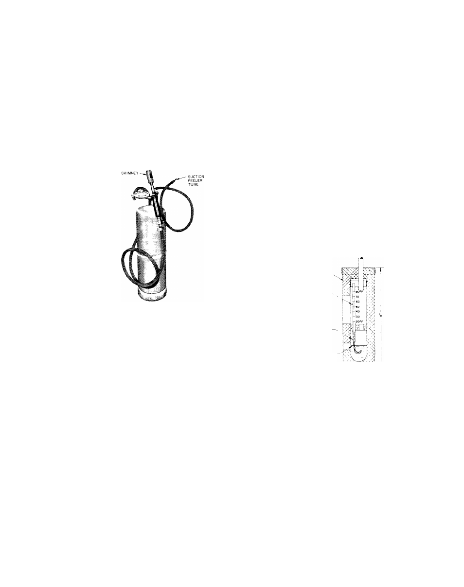
The Halide Leak Detector
The Halide Leak Detector pictured in Fig. 23
consists of a burner, needle valve, suction tube,
and
a
chimney
with
a
copper
reaction
plate.
Some torches use alcohol and others use pro
pane fuel.
/Ч, '
Fig. 23 - Halide Leak Detector
To use the leak detector;
1.
Adjust the flame so the top of the flame cone
is level with or slightly above the chimney.
2.
Place the end of the suction tube at the point
to be tested. The tube pulls in a sample of
air to the burner where the refrigerant is de
composed by reaction with the copper plate.
3.
Observe the color of the flame. Small leaks
give a greenish tint and large ones a vivid
blue. Leaks can also be detected with a soap
solution or an electronic gun.
DEHYDRATE THE SYSTEM
If there has been a leak in the 30HH unit or after
field piping the 30HJ unit, the system must be
evacuated.
Moisture
in
the
system
causes
oil-sludge
and
corrosion, it is likely to freeze up the expansion
valve
of
a
low
temperature
system.
The
best
means of dehydration is evacuation with a pump
specially built for this purpose.
Preparation
Before dehydrating a system make the following
preparations:
1.
Obtain a pump that will produce a vacuum of
.2" Hg absolute. Do not use the compressor
as a vacuum pump. It is not designed for such
use and may be seriously damaged.
2.
Pressure test system to be sure it is free of
leaks.
3.
Obtain a vacuum indicator similar to that
shown in Fig. 24 (available thru local Carrier
Distributor).
4.
Keep the ambient temperature above 60 F to
speed the evaporation of moisture.
и
1 SAE PLUG
, -
. ,
l."SAE FLARE NUT----------------S--------------r*
u
I »SOLATIO«-
TME«MC«ETEft
distilled
WATER
L.. J T
Fig. 24 - Vacuum Indicator
Description and Use of the Vacuum Indicator
The
vacuum
indicator
consists
of
a
wet
bulb
thermometer in an insulated glass tube contain
ing distilled water. Part of the tube is exposed
so the thermometer can be read and the water
level
checked.
When
the
vacuum
indicator
is
connected to the vacuum pump suction line, the
thermometer reads the temperature of the water
in the tube. The temperature is related to the
absolute
pressure
in
the
tube.
Table
7
gives
the
absolute
pressures
corresponding
to
var
ious temperatures.
¿HahdlQ the vacuum indicator with care. It must
be vacuum tight to give a true reading. The top
17