Storage, Location, Space requirements and clearance – Carrier 30HH User Manual
Page 6: Adequate floor strength, Vibration isolation, Moving and placing unit, Moving, 30hh,hj, Installation
Attention! The text in this document has been recognized automatically. To view the original document, you can use the "Original mode".
30HH,HJ
INSTALLATION
PRELIMINARY SURVEY
Before
installation
is
started,
a
survey
should
be made to establish the procedures and ma
terials
required
by
installation
personnel.
See
cover picture for typical unit.
Storage
Because of the sensitive control mechanisms and
electrical
devices
incorporated
in
the
30HH,HJ
units, they should not be exposed to the weather.
Location
Always locate the unit indoors. In order to pre
vent freezing, the unit must be located in a space
where the temperature is at least 40 degrees.
Space Requirements and Clearance
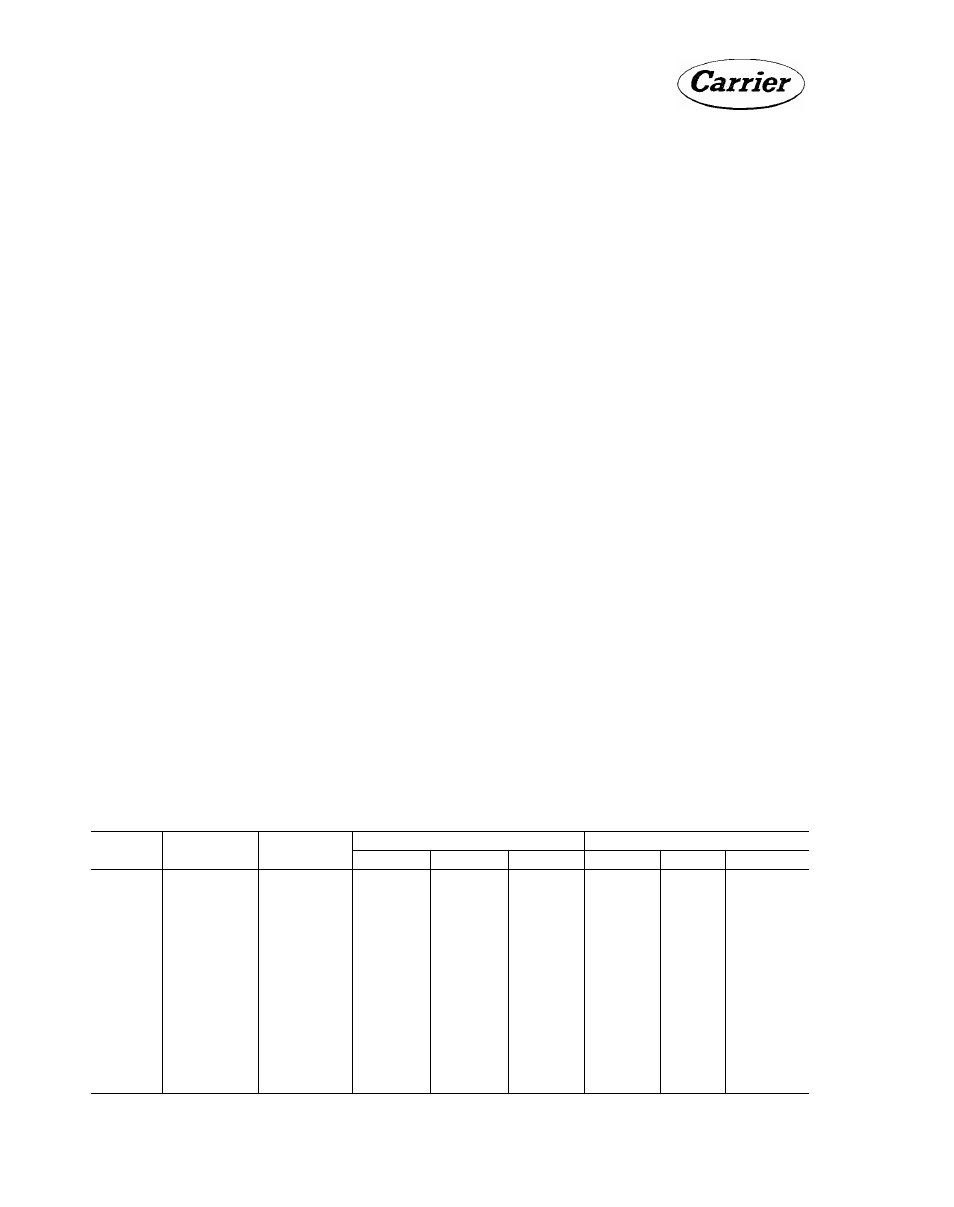
Dimensions for the units are given in Table 1.
These
dimensions
are
useful
in
checking
door
clearances for moving the unit in and for deter
mining space requirements. A clearance of 2 to
3 feet should be left on each side and on the ends
for
piping
and
electrical
connections
and
also
to
facilitate
service
operations.
Clearance
at
one end of the unit, equal to the length of the
unit, for servicing and removal of chiller tubes
must be provided.
Adequate Floor Strength
Approximate weights of units are given in Table
1.
Make certain that the floor is strong enough
to support this weight. If necessary, add sup
porting
structure
to
the
floor
for
transferring
weight to the nearest beams. This can be done
with steel beams or reinforced concrete slabs.
Vibration Isolation
Rubber-in-shear
vibration
insulators
and
muf
flers
are
installed
on,
or
furnished
with,
the
compressors
of
all
units
beginning
with
early
1961
production.
The
inter-connecting
piping
must
be
sufficiently
flexible
to
prevent
vibra
tion
transmission,
if
vibration
still
exists,
vi
bration isolators may be used on the unit itself.
The
field-purchased
vibration
mountings
should
be placed under each corner of the package. The
weight
distribution
of
all
packages
except
the
30HH015 and 30HJ015 is such that each corner
mounting
supports
one
fourth
of
the
operating
weight. The weight distribution of the 30HH015
and 30HJ015 units is 55-45 side to side and sym
metrical front to back.
All phases of vibration isolation are fully de
scribed in Section 5X-1 of the Product Infor
mation book. Consult same for best results.
For
additional
information
see
"Compressor
Mounting."
MOVING AND PLACING UNIT
Moving
The skids on which the unit is mounted should
not be removed until the unit is at the final loca
tion. When handling the unit with a chain hoist,
remove the panels so that they will not be dam
aged by the sling. Do not attach the sling to
Table 1 - Weight and Overall Dimensions - 30HH.HJ Liquid Chiller Package
Unit
Shipping
Wt. (lbs.)
Operating
Wt. (lbs.)
Uncrated Dimensions (Ins.)
Crated Dimensions (Ins.)
Length
Width
Height
Length
Width
Height
30HH015
1430
1625
72
22-1/2
54-3/4
76
30
63
30HH020
2200
2150
72
22-1/2
54-3/4
76
30
63
30HJ015
1270
1460
72
22-1/2
47
76
30
63
ЗОН] 020
1700
1800
72
25-1/2
47
76
30
63
30HH025
2200
1950
72
22-1/2
54-3/4
76
30
63
30HH030
2550
1950
72
22-1/2
54-3/4
76
30
63
30H]025
2100
1800
72
25-1/2
47
76
30
63
30HJ030
2150
1850
72
25-1/2
47
76
30
63
30HH045
3010
3391
79-1/4
29-1/4
79
83-1/2
33
84-7/8
30HJ045
2455
2835
•79-1/4
29-1/4
66
83-1/2
33
84-7/8
30HH055
4622
5158
105-1/4
29-1/4
80-3/8
109-3/4
33
86-3/4
30HH065
4700
5236
105-1/4
29-1/4
80-3/8
109-3/4
33
86-3/4
30HJ065
3700
4236
105-1/4
29-1/4
У6
109-3/4
33
86-3/4