Drain connection, Cooler water piping, 30hh,hj – Carrier 30HH User Manual
Page 14: Installation
Attention! The text in this document has been recognized automatically. To view the original document, you can use the "Original mode".
30HH,HJ
INSTALLATION
Drain Connection
Drain
connections
are
generally
governed
by
local
codes.
Water
leaving
the
condenser
is
under
pressure
and
should
not
be
connected
directly
into
sewer
lines;
otherwise
water
may
back up into other fixtures. Local codes nor
mally
require
connections
similar
to
the
one
shown in Fig. 17.
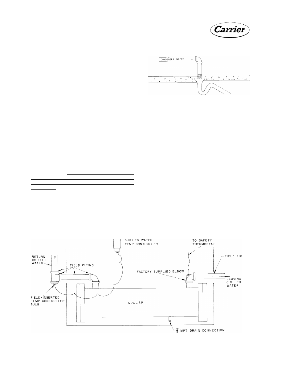
COOLER WATER PIPING
The cooler of each liquid chilling package is pro
vided with stubouts for chilled water piping con
nections.
The
water
outlet
stubout
is
provided
with a 90 degree elbow which contains the chilled
water
safety
thermostat
bulb.
Holes
are
pro
vided in both of the side panels for piping to the
stubouts.
The
chilled
water
temperature
controller
is
mounted on the front of the unit and has the con
trol bulb and capillary tubing wrapped and taped
before shipping. It is required that the control
bulb be field inserted in the chilled water line.
It usually is inserted in the return or inlet chilled
water piping. Figure 18 shows a typical chilled
water piping arrangement in the vicinity of the
cooler.
Details
of
the
required
remote
chilled
water piping are outlined in the Carrier System
Design Manual, Part 3, "Piping Design."
Plan the piping so it has a minimum number of
changes
in
elevation.
A
manual
or
automatic
Fig. 17 - Drain Connections
vent-valve must be installed at the high points
in the line to permit venting of air from the
chilled
water
circuit.
Standard
practice
for
in
stalling forced water systems must be followed.
System pressures may be maintained by using a
pressure tank or a combination relief valve and
reducing valve.
It
is
recommended
that
thermometers
be
in
stalled
in
entering
and
leaving
chilled
liquid
lines. Provide drain connections at all low points
to permit complete drainage of the system. A
chiller drain shut-off valve should be connected
to the chiller drain line before placing the unit
in operation (Fig. 18).
Insulate piping to prevent heat loss and sweating.
Cover the insulation with a moisture seal. Do
not insulate piping before all leak testing has
been completed.
Fig. 18 - Cooler Water Piping, Front View
14