High and low pressure controls, 30hh,hj, Installation – Carrier 30HH User Manual
Page 22
Attention! The text in this document has been recognized automatically. To view the original document, you can use the "Original mode".
30HH,HJ
INSTALLATION
glycols or brines are to be cooled. The adjust
ment tolerance is commonly j- 1 F.
DAMAGE DUE TO THE FREEZING OF A CHILL -
ER IS NOT COVERED BY THE WARRANTY.
The
safety
thermostat
bulb
is
located
in
the
leaving chilled water piping stubout.
IMPORTANT:
This
thermostat
should
be checked at the time of installation
and at least once every season. If the
bulb is damaged in handling, its cali
bration may be off.
To check the safety thermostat:
1.
Place the thermal bulb in a vacuum bottle
filled with water and add crushed ice.
NOTE: This is an insert type bulb. On
earlier units, removal opens water sys-
except on 30HH,HJ045 thru 065 units
which use a sealed well. Later units
all use a sealed well.
2.
Stir
the
contents with
a thermometer and
note the temperature at which safety thermo
stat cuts out.
3.
Reset the safety thermostat if necessary. To
set the control, use screwdriver in slot and
rotate
dial
until
the
desired
temperature
at
which compressor is to stop is directly under
indicator "B”.
To recalibrate the safety thermostat;
1.
Measure the temperature as close to the bulb
as
possible,
immediately
after
the
compres
sor stops.
2.
Break the painted seal between the dial and
the adjusting plate with a knife.
3.
Carefully loosen the two dial screws. Be care
ful not to turn the brass cylinder below the
dial during this or any of the following oper
ations.
4.
Turn the dial ONLY so that the fixed indica
tor
points
to
thè
temperature
measured
at
step 1.
5. Carefully tighten the dial screws.
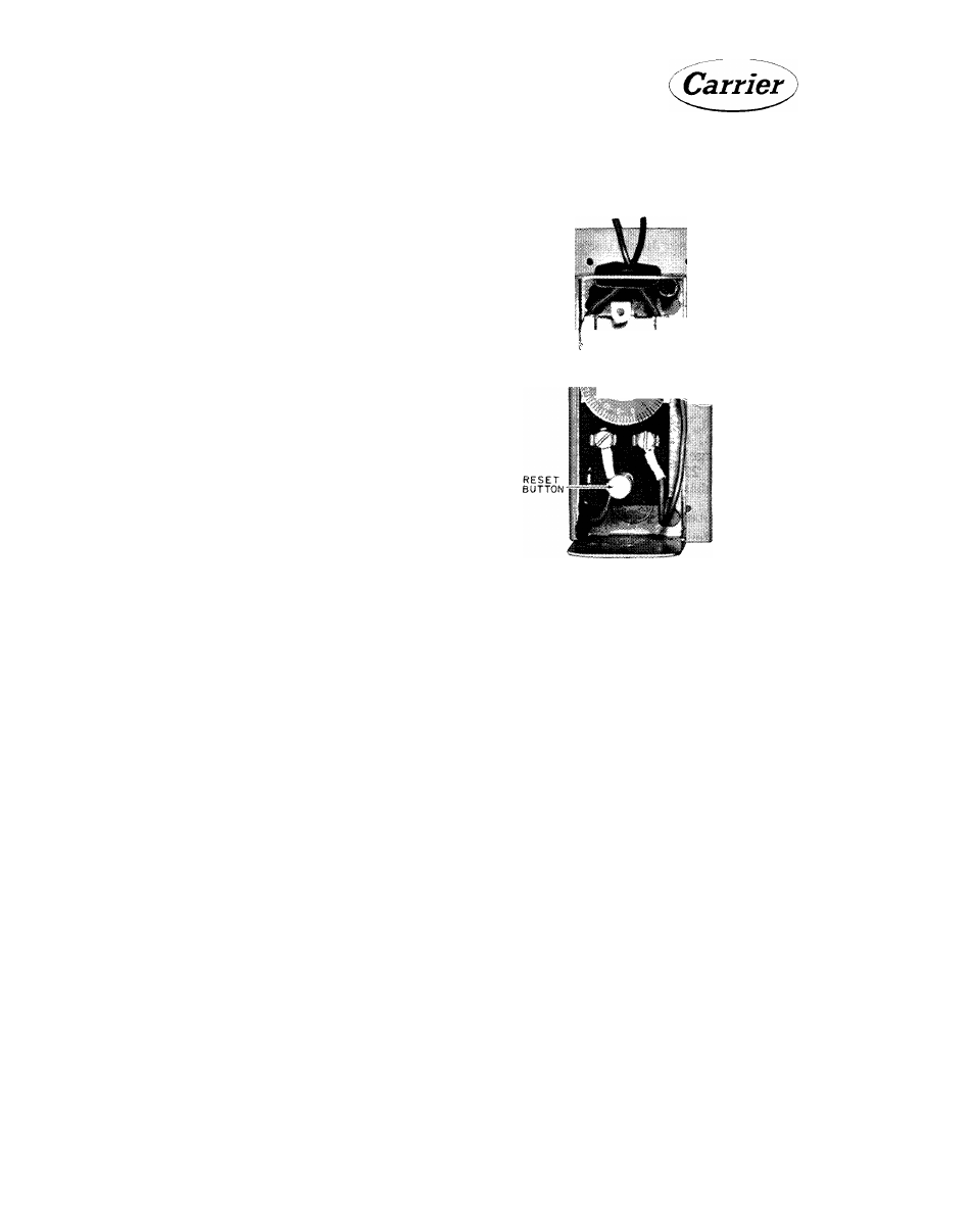
I ‘-f
FIXED IMDICATOR
ADJUSTING SLOT
Fig. 27 - Safety Thermostat
High and Low Pressure Controls
Pressure control settings are shown in Table 8.
The 30HJ high pressure control settings are suit
able for use with either air-cooled or evaporative
condensers. The control setting (Table 8) is a
fixed setting and is nonadjustable.
Check the high pressure switch setting by slowly
closing the discharge shut-off valve. The com
pressor
should
shut
down
when
the
discharge
pressure reaches 260 or 355 psi (as required)
and start up when the pressure drops to 210, or
255 psi (as required).
The 30HH high pressure switches are adjustable
and equipped with a stop to prevent field setting
above 280 lbs.
To
check
the
low
pressure
switch,
close
the
suction shut-off valve and allow the compressor
to pump down. The compressor should cut out
when the suction pressure falls to 46 psig, and
automatically
start
up
again
when
the
suction
pressure builds up to 83 psig.
Both sides should be checked at startup and at
least once a year thereafter.
22