Condenser water piping, Frangible disc safety union, 30hh,hj – Carrier 30HH User Manual
Page 11: Installation
Attention! The text in this document has been recognized automatically. To view the original document, you can use the "Original mode".
INSTALLATION
30HH,HJ
FRONT
MOTOR END
REAR
PUMP END
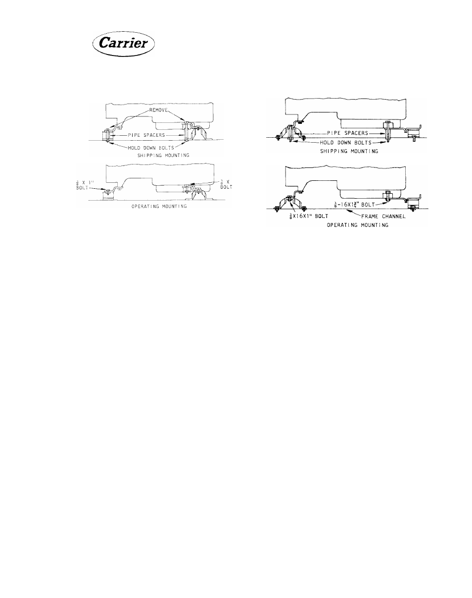
Fig. 8 - 30HH,HJ015-030 Compressor
Mounting
Fig. 9 - 30HH,HJ045-065 Compressor
Mounting
7.
Remove both compressor motor end hold
down
bolts,
nuts,
lock
washers,
and
pipe
spacers, and replace with 3/8-16 x 1” bolts.
Reinstall
lock
washers
and
nuts
to
fasten
mounting brackets to resilient mounts.
30HH,HJ045 to 065 units (Fig. 9):
The pairs of manifolded compressors are mount
ed on common mounting brackets. Be sure all
pipe spacers are removed for proper operation.
The mounting of the single compressor on
30HH,HJ045 units is similar.
1.
Remove one 3/8-16 x 3-1/2” hold-down bolt,
nut, lock washer, and pipe spacer on the pump
end of the compressor.
2.
Install a 3/8-16 x 1-3/4” bolt, supplied in
bag of fastenings, and reinstall nut and lock
washer from hold-down bolt, to fasten com
pressor to mounting bracket.
3.
Repeat steps 1 and 2 for the other pump end
fastenings of the compressors.
4.
Remove one 3/8-16 x 2-1/2” hold-down bolt,
nut, lock washer and pipe spacer on the motor
end of the compressor.
5.
Install a 3/8-16 x 1” bolt, supplied in bag of
fastenings, and reinstall nut and lock washer
from
hold-down
bolt
to
fasten
mounting
bracket to resilient mount.
6. Repeat steps 5 and 6 for the other motor end
fastenings of the compressor.
CONDENSER WATER PIPING
Water supply lines should be as short as condi
tions will permit. The size of these lines is not
necessarily the same as those of the water valve
connections. All piping must be sized in accord
ance with tije pressure head available. This is
especially
true
on
cooling
tower
applications.
See the System Design Manual, Part 3- "Piping
Design” for methods used in sizing pipe.
For installations using a waste water system, a
separate
water
regulating
valve
is
required
for
each
refrigerant
circuit.
Water
regulating
valves
are not supplied by Carrier.
NOTE: Provide means for draining the
system in the winter and for repairs.
Figure 10 thru 16 show suggested piping
connections for each model when used
with waste water or cooling towers.
Frangible Disc Safety Union
Each
condenser
is
provided
with
a
frangible
disc that will relieve at 385 psig to protect the
system from excessive pressure.
Some local codes require piping from the relief
to the outdoors. The relief outlet size on both
models is 3/8” male flare.
11
1064