Compressor mounting, 30hh,hj, Carrier – Carrier 30HH User Manual
Page 10: Installation
Attention! The text in this document has been recognized automatically. To view the original document, you can use the "Original mode".
30HH,HJ
INSTALLATION
Carrier
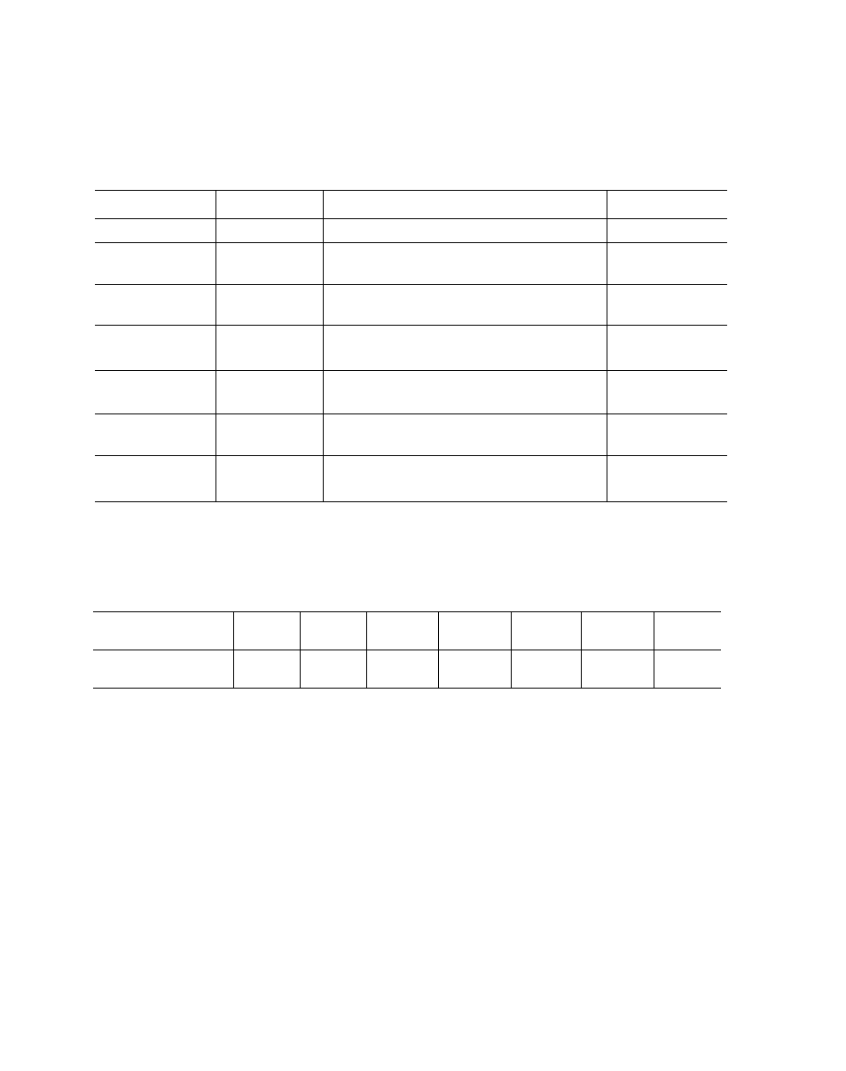
Table 5 - Refrigerant Circuits
Unit Size
Circuits
Description of Refrigerant Circuit
Capacity (%)
зоны, HJ015
1
(i) 6D73 or 6D75 Compr, Full Cooler Surface
100
(1) 6D68 Compr, 1/2 Cooler Surface
50
30HH, HJ020
2
(1) 6D68 Compr, 1/2 Cooler Surface
50
(1) 6D68 Compr, 1/2 Cooler Surface
40
зоны, HJ025
2
(1) 6D73 or 6D75 Compr, 1/2 Cooler Surface
60
(1) 6D73 or 6D75 Compr, 1/2 Cooler Surface
50
ЗОНЫ, HJ030
2
(1) 6D73 or 6D75 Compr, 1/2 Cooler Surface
50
(1) 6D73 or 6D75 Compr, 1/3 Cooler Surface
33
ЗОНН, HJ045
2
(2) 6D73 or 6D7S Compr, 2/3 Cooler Surface
67
(2) 6D73 Compr, 1/2 Cooler Surface
55
30НН055
2
(1) 6D73 & (1) 6D68 Compr, 1/2 Cooler Surface
45
(2) 6D73 or 6D75 Compr, 1/2 Cooler Surface
50
ЗОНН, HJ065
2
(2) 6D73 or 6D75 Comipr, 1/2 Cooler Surface
50
NOTE: 6D73 Compressors arc used on ЗОНЫ models. 6D75 Compressors are used on 30HJ miodels.
Table 6 - Refrigerant Charge
Model ЗОНН, HJ
015
020
025
030
045
055
065
Refrigerant 22 (lb)
35
46
46
46
69
124
140
NOTES: 1. The refrigerant charges listed above do
not include the additional charge required
for remote condensers and piping with
ЗОН] models.
2. The 30HH015 and 30HH020 units are
shipped fully charged with refrigerant.
Other units are shipped with holding
charges only.
COMPRESSOR MOUNTING
All 30HH,HJ chillers, as shipped, have the com
pressor rigidly mounted to the frame with bolts
and
steel
pipe
spacers.
For
proper
operation,
the following procedure should be followed;
30HH,HJ020 to 030 units (Fig. 8):
1. Loosen the four (4) hold-down bolts on one
compressor.
2. Remove one hold-down bolt, lock washer
and nut on oil pump end of compressor. Lift
end of compressor and remove pipe spacer.
3.
Tighten hold-down bolt which is diagonally
opposite spacer which was removed.
4.
Install 3/8-16 X 1-1/2" bolt, supplied in bag
of
fastenings,
between
compressor
foot
and
bracket. Reinstall lock washer and nut.
5. Loosen hold-down bolt tightened in step No. 3.
6.
Repeat steps 2 thru 5 for other oil pump end
bolt.
10