Refrigerant piping, 30hh,hj, Carrier – Carrier 30HH User Manual
Page 15: Installation
Attention! The text in this document has been recognized automatically. To view the original document, you can use the "Original mode".
Carrier
INSTALLATION
30HH,HJ
REFRIGERANT PIPING
For refrigerant piping sizing refer to Part 3 -
’’Piping Design” - of the System Design Manual.
The ЗОНЫ and HJ Packaged Liquid Chillers are
leak tested at the factory and provided with a
holding charge of Refrigerant 22.
NOTE: 30HH015,020 fully charged with
R 22 at factory.
If the holding charge is still in the system upon
arrival at the erection site, the likelihood of leaks
is slight. If the unit is not under pressure, test
for leaks as outlined under Leak Testing.
NOTE: Be sure to open all stop valves
when testing for leaks.
30HJ UNIT
This section also applies to the 30HJ unit which
is to be connected to a remote condenser in the
field. Figure 19 is a typical refrigerant piping
diagram showing the 30HJ020 thru 030 unit and a
9H
Evaporative
Condenser.
Simdlar
connections
may be used for the 30Ш045 and 065 unit using
manifolded
compressors.
Figure
20-22
illus
trate typical refrigerant piping for 30HJ020 thru
065
units
and
air-cooled
condensers.
Receivers
have been omitted, but it must be recognized
that with this arrangement the refrigerant charge
is
critical.
An
overcharged
or
undercharged
system can cause a loss of capacity. If a receiver
is
not
Included,
an
accurate
refrigerant
charge
must be maintained to assure efficient operation.
Figure 20-22 are shown to illustrate a typical
installation using 9A or 09DC016 air-cooled con
densers. These illustrations are to be used as a
guide when designing a system and are not in
tended to be used as an actual piping layout. Con
sult the ’’System Design Manual” and condenser
literature before designing the actual system.
Each 30HJ unit (except -015) consists of two
independent
refrigerant
circuits.
Each
circuit
must be isolated from the other.
Discharge lines and liquid lines are shown mani
folded at the units on 30HJ045 and 065 units to
permit a minimum amount of piping. Individual
discharge lines may be run from each compres
sor to the condenser if desirable. Liquid lines
must be manifolded as shown to enter the 30HJ065
unit to agree with the unit refrigerant circuit. In
dividual liquid line connections are necessary on
the 30HJ045 unit.
F R O M T A B L E - F O R V E N T I N G A S S H O W N
M U F F L E R S S H O U L D
A S P O S S I S L E .
I N S T A L L E D A S C L O S E T O T H E C O M P R E S S O ч
U N I T
“ X ” D I M . *
3 0 H U 0 1 5
6
"
3 Û H J 0 2 0
1 5 "
3 0 H J 0 2 5
1 5 "
3 0 H J 0 3 0
1 5 "
3 0 H U 0 A 5
1 5 "
3
O H J O
6 5
1 5 "
" X " D I M . - T H I S I S
T H E M I N I M U M , E L E V A T I O N
R E Q U I R E D B E T W E E N A
C O N D E N S E R C O I L O U T L E T
A N D A R E C E ! V E R I N L E T
F O R T H E T O T A L L O A D
W H E N R E C E ; V E R 1 S
V E N T E D T O C O I I . O U T L E T
H E A D E R ( B A S E D O N 1 0 '
O F H O R I Z O N T A L P I P E ,
1 V A L V E A N D 2 E L B O W S ) .
A P P L I E S T O 9 H T Y P E
E V A P . C O N D E N S E R
- R E F R I G . G A S
- R E F I G . L I Q U I D
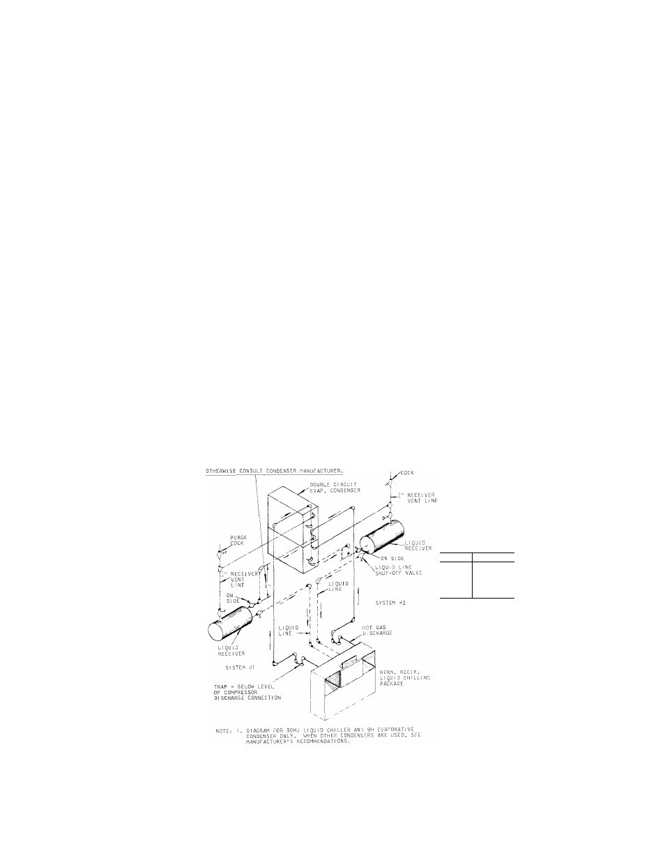
Fig. 19 - Typical Refrigerant Piping 30HJ020-030 Units
with 9H Evaporative Condenser
15