Installation, Water regulating valve, Temperature controller adjustment – Carrier 30HH User Manual
Page 24: 30hh,hj, Carrier
Attention! The text in this document has been recognized automatically. To view the original document, you can use the "Original mode".
30HH,HJ
INSTALLATION
Carrier
Two eight ampere fuses protect the control cir
cuit against overload. The control light will be
on
whenever
the
control
circuit
is
energized.
Disengage the fuse caps to remove blown fuses.
The "X" values (Table 10) were established by
experimentation and are such that the compres
sor is prevented from cycling more than once
in a five minute period.
Fig. 28 - Gauge Panel (30HH,HJ045)
The throttling range is determined as follows;
Throttling Range (modulating) =
Design Rise + "X”
The
throttling
range
setting
is
arrived
at
by
entering the graph below at the "set point” and
moving across an amount equal to the throttling
range. The setting is read from the top scale
and will fall somewhere between min. - F. To
illustrate, with a 30HH065 Chiller, a 4-compres
sor unit, at a 10 F design rise, 45 F leaving
chilled
water
temperature,
the
set
point
would
be 45 - 1 = 44 F. The throttling range would be
10 + 1 = F.
Entering the graph at 44 F and moving across
11
F indicates a throttling range setting of just
under "A”.
Table 10 - ”X” Values, F
WATER REGULATING VALVE
The
water
regulating
valve
should
be
set
to
maintain the most economical head pressure as
determined by the design engineer, based on the
relative cost of water and electricity in a given
area. It should not be adjusted to compensate
for high head pressures caused by fouled con
denser
tubes,
excess
refrigerant
or
the
pres
ence
of
noncondensables.
Due
to
changes
in
water
temperatures,
it
may
be
necessary
to
adjust
the
valve
seasonally.
After
adjusting
for
the
economical
head
pressure,
the
machine
should be shut down. The water regulating valve
should shut off the flow of water in a few min
utes. If it does not, it will be necessary to
raise the head pressure setting. The water reg
ulating
valve
is
used
for
city
water
and
in
some
cases
with
multiple
units
on
a
single
cooling tower.
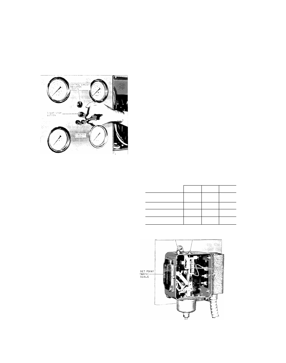
TEMPERATURE CONTROLLER ADJUSTMENT
The
chilled
water
temperature
controller
must
be
adjusted
in the field before initial startup.
Two adjustments are required - Set Point (main
scale, 15 - 90 F) and Throttling Range (modu
lating, min - F).
The set point is determined as follows ;
Set Point = Design Leaving Chilled Water
Temperature - ”X”
Design Rise F
No. of Comp.
8
10
12
1
2.0
2.5
3.0
2
2.0
2.5
3.0
3
1.25
1.5
1.75
4
.75
1.0
1.25
S E T P O I N T
A D J U S T M E N T S C R E W
T H R O T T L I N G R A N G E ( M O D U L A T I N G )
^ A D J U S T M E N T S C R E W
T H R O T T L I N G
R A N G E
S C A L E
Fig. 29 - Chilled Water Temperature
Controller
24