30hh,hj, Installation – Carrier 30HH User Manual
Page 16
Attention! The text in this document has been recognized automatically. To view the original document, you can use the "Original mode".
30HH,HJ
INSTALLATION
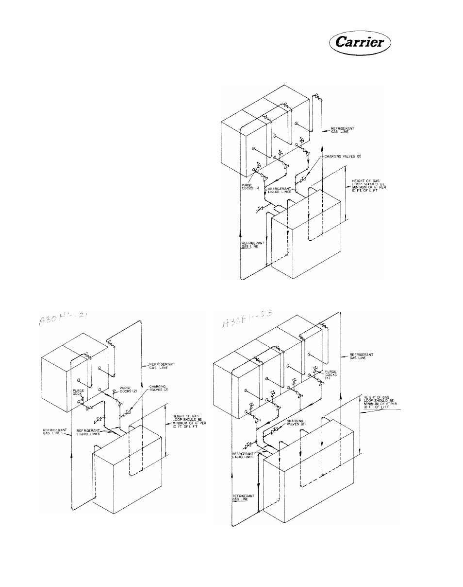
In order to prevent condensed liquid refrigerant
or oil from causing damage to the compressor,
install a trap in the vertical discharge line near
the compressor. The trap may be installed within
or adjacent to the unit base. The height of the
trap (or loop) should be 6 inches for every 10
feet of vertical discharge line. If the height of
the vertical discharge line is such as to make
a single trap impractical, the loop can be re
placed by a check valve or several traps.
To prevent the formation of copper oxide when
brazing copper tubing, bleed a small amount of
dry nitrogen gas thru the piping. The nitrogen
will displace the air containing oxygen.
Complete
all
field
piping
before
removing
the
seals on the unit refrigerant piping. Upon com
pletion of the field piping, add a small amount
of
refrigerant
and
build
up
the
required
test
pressure with dry nitrogen or other inert gas.
If
a
test
pressure
is
not
specified,
ASA-B9
Code calls for 300 psig high side and 150 psig
low side test pressures for R 22.
NOTE: 1. Install mufflers as close to compres
sor discharge valve as possible.
2.
Make sure a pressure relief device is
installed in the hot gas line or con
denser used with the 30HJ models.
Fig. 21 - Rafrigerant Piping to Three Air-
Cooled Condensers 30HJ045 (without Receivers)
Fig. 20 - Refrigerant Piping to Two Air-
Cooled Condensers 30HJ020,025,030
(without Receivers)
Fig. 22 - Refrigerant Piping to Four Air-
Cooled Condensers 30HJ065 (without Receivers)
16