Top Flite TOPA0700 User Manual
Page 6
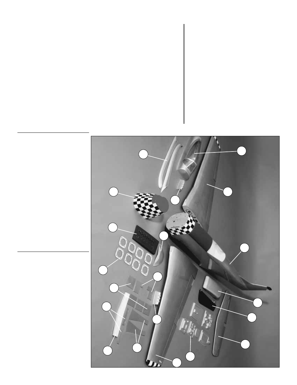
KIT INSPECTION
Bef
ore star
ting to b
uild, tak
e an in
ventor
y of this kit to
mak
e sure it is complete
, and inspect the par
ts to mak
e
sure the
y are of acceptab
le quality
.
If an
y par
ts are
missing or are not of acceptab
le quality
, or if y
ou need
assistance with assemb
ly
, contact
Pr
oduct Suppor
t.
When repor
ting def
ectiv
e or missing par
ts
, use the par
t
names e
xactly as the
y are wr
itten in the kit contents list
on this page
.
T
op Flite Pr
oduct Suppor
t
3002 N Apollo Drive Suite 1
Champaign,
IL 61822
T
e
lephone:
(217) 398-8970
F
ax:
(217) 398-7721
E-mail:
P
A
R
TS PHO
T
OGRAPHED
1
.
Fuselage
2
.
Rudder
3
.
Canop
y
4
.
Fiberglass co
wl
5
.
Fiberglass air scoop
6
.
Fiberglass wing f
air
ing
7
.
Coc
kpit par
ts
8
.
T
ail gear doors
9
.
Wing joiner
10
.Landing gear co
v
e
rs
11
.
Wings with flaps & ailerons
12
.
Hor
iz
ontal stabiliz
er with ele
v
ators
13
.
(2) Fiberglass wing fillets
14
.
(2) Plastic machine guns
15
.
(2) Plastic engine e
xhaust outlets
16
.
(8) Engine mount spacers
17
.
Wheel co
v
ers
18
.
Ser
v
o
hatches
P
A
R
TS NO
T PHO
T
OGRAPHED
sheet-metal scre
ws:
(34) #2 x 3/8" (24-wing ser
v
o
hatches
, 6-landing
gear co
v
e
rs
, 4-wheel co
v
ers)
(28) #4 x 1/2" Phillips-head (24-all control hor
ns
e
xcept r
u
dder
, 4-tail gear mounting)
(8)
#4 x 5/8" Phillips-head (4-r
udder control hor
n,
4-co
wl mounting)
(12) #6 x 1/2" (landing gear mounting)
(8)
#2 x 1/2" (2-landing gear co
v
e
rs
, 2-fuel tank
floor
, 4-f
orw
ard ser
v
o tr
a
y
)
(8)
#2 x 3/16" (canop
y mounting)
mac
hine scre
ws:
(4) 2-56 x 3/8" (tail gear door br
ac
k
ets)
(4) 4-40 x 3/8" (4-co
wl reinf
orcement glue on)
pushr
ods:
(4) 4-40 x 4" wire pushrods (2-ailerons
, 2-flaps)
(3) 4-40 x 36" wire pushrods (2-ele
v
ators
, 1-r
udder)
(6) 3/16" pushrod guide tubes (5-f
actor
y-installed in
fuselage
, 1-throttle)
(1) 36" white
, plastic pushrod (throttle)
(1) 2-56 x 4" pushrod (air v
alv
e)
n
y
lon har
d
ware:
(7) large control hor
ns (2-ailerons
, 2-flaps
,
2-ele
v
ators
, 1-r
udder)
(2) 1/4-20 x 2" n
ylon wing bolts
(1) ball link (throttle)
(2) n
ylon cle
vis (1-throttle
, 1-air v
alv
e)
(14) pinned hinge points (f
or ailerons and flaps)
metal har
d
ware:
(7) 4-40 threaded metal cle
vises (2-ailerons
,
2-flaps
, 2-ele
v
ator
, 1-r
udder)
(7) Large solder cle
vises (2-ailerons
, 2-flaps
,
2-ele
v
ator
, 1-r
udder)
- 6
-
1
2
12
5
3
4
15
16
17
9
14
14
13
8
18
6
10
11
11
7