Top Flite TOPA0700 User Manual
Page 15
❏❏
R5.
Use coarse sandpaper to thoroughly
roughen the inside of the fiberglass wheel co
v
e
r
where the br
aces will go
.
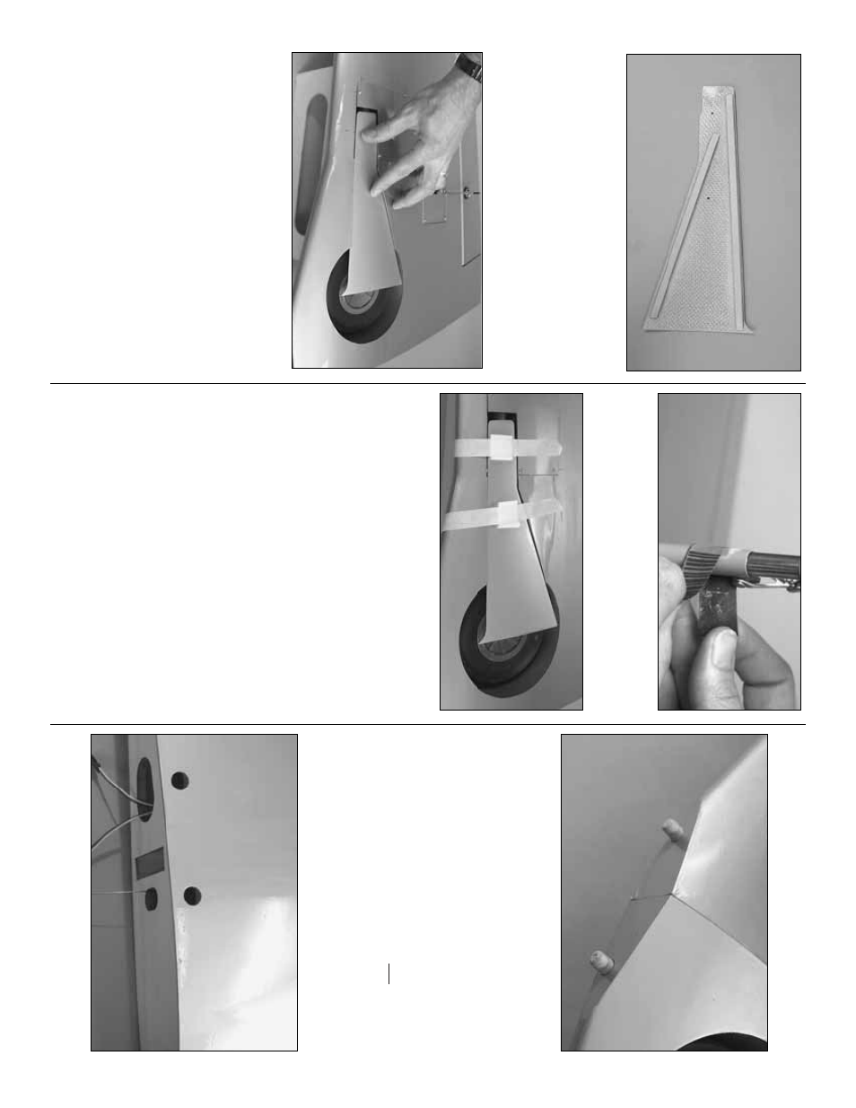
Cut tw
o
braces
from a
3/32" x 1/4" x 19-1/2" [2 x 6 x 500mm] hardw
ood stic
k
to the length sho
wn in the photo
.
Use medium CA to
glue the br
aces into position.
The br
aces should be
inset 1/16" from the edges of the wheel co
v
e
r.
❏❏
R6.
Reposition the mounts on the str
ut.
Place
the fiberglass
wheel co
ver
on the mounts
.
The
wheel co
v
er should be e
v
en with the bottom of the
wing.
If necessar
y,
mak
e adjustments to the angle
cut on the mounts until the wheel co
v
e
r fits
.
If y
o
u
end up cutting the mounts too shor
t, tr
y again with
the e
xtr
as pro
vided.
❏❏
R7.
The same w
a
y y
ou dre
w the ref
erence mar
ks
for dr
illing the holes in the hatch, mar
k and dr
ill the
holes in the wheel co
ve
r and the wheel co
ver mounts
.
❏❏
R8.
Mount the wheel co
v
er to the mounts with
tw
o #2 x 3/8" [9.5mm] scre
ws and #2 w
ashers
.
❏❏
R9.
Use a 1/2" [15mm] str
ip of coarse
sandpaper to remo
v
e the paint and roughen the
str
uts where the mounts go
.
❏❏
R10.
With the wheel co
v
ers still attached to the
wheel co
v
er mounts
, glue the mounts to the str
uts
with 30-min
ute epo
xy
.
Use masking tape with pieces
of R/C f
oam under
neath to hold the mounts to the
str
uts and to hold the wheel co
v
ers in position.
❏❏
R11.
After the epo
xy from the pre
vious step
has fully hardened, remo
v
e
the tape and e
xtend the
gear b
y
hand.
Mak
e
cer
tain that the gear can oper
ate
freely and that there is no interf
erence betw
een the
wheel co
v
er and the wing.
If necessar
y,
tr
im the
wheel co
v
er f
or a good fit, and/or adjust the height
and angle of the wheel co
v
er b
y
gluing thin balsa
“shims”
to the top of the wheel co
v
er mounts
.
❏❏
R12.
Use one of y
our paper to
w
el squares
dampened with denatured alcohol to wipe the ref
erence
dr
a
wn on the bottom of the wing.
Remo
ve
the wheel
co
ve
r.
Add a f
e
w drops of thin CA to the holes in the
wheel co
ver mounts
.
Remount the wheel co
vers
.
❏
R13.
Retur
n to step one and repeat the procedure
to mount the hatch and wheel co
ver to the other gear
.
Install the air lines
❏
R1.
Bef
ore installing the air lines
, cut the co
v
e
ring
from the hole in the front of both wing halv
es f
or the
3/8" [10mm]
wing do
wels
.
Glue the do
w
els in with
30-min
ute epo
xy
.
(The wings in the photo are joined,
b
ut y
our wings should not y
et be joined.)
No
w to the air lines (star
t with the left
wing)…
❏❏
R2.
Remo
v
e
the retr
act hatch and the retr
act
from the left wing.
Add a f
e
w drops of thin CA to the
scre
w holes
.
❏❏
R3.
Cut the co
v
e
ring from the holes in the top
of the wing f
o
r the ser
v
o
wires and the air line tubing.
- 15
-