Top Flite TOPA0700 User Manual
Page 13
❏❏
2.
Thread a 4-40 n
ut and a 4-40 metal cle
vis to
the other end of the pushrod.
Connect the pushrod to
the aileron ser
v
o
ar
m and to a
lar
g
e contr
ol horn
.
P
osition the hor
n on the aileron directly behind the
ar
m.
The base of the hor
n should be set bac
k from
the tr
ailing edge of the wing 1/4" [6mm].
Dr
ill 3/32"
[2.4mm] holes into the aileron f
o
r the hor
n.
Mount the
hor
n with f
our #2 x 1/2" [13mm] scre
ws
.
Adjust the
length of the pushrod b
y
tur
ning the cle
vis so the
aileron will be neutr
al when the ser
v
o
is centered
(this will be fine-tuned later when setting up the r
adio
,
so there is no need to tighten the 4-40 n
u
t to the
cle
vis until then).
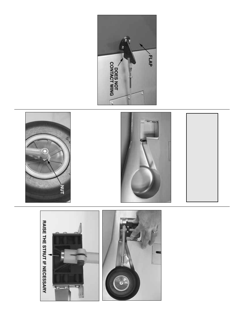
❏❏
3.
Hook up the flap the same w
a
y.
Note that the
flap is retr
acted (“up”) when the ser
v
o
ar
m is rotated
aft (not when the ser
v
o
ar
m is centered).
Be cer
tain
the control hor
n is set bac
k f
ar enough so it will not
contact the wing at full flap deflection.
❏❏
4.
One last
IMPOR
T
ANT
step;
remo
ve the scre
w
s
from both ser
vo
hatches and both control hor
ns
.
Add a
fe
w drops of thin CA to all the holes
, allo
w to
full
y
harden.
Remount the hatches and hor
ns
.
❏
5.
Mount the hatches and hook up the aileron and
flap on the r
ight wing the same w
a
y.
Mount the retracts
Install the left retract fir
st.
❏❏
R1.
The same as the co
ve
ring w
as cut from the
aileron hatches
, cut the co
ve
ring from the landing gear
opening 1/4" [5mm] inside the edges all the w
a
y around
the opening.
Use a tr
im iron to iron do
wn the co
ve
ring.
❏❏
R2.
Enlarge the hole in the Du-Bro 5" [127mm]
wheels (not included) with a siz
e
“F”
[6.5mm] (or
17/64" [6.8mm]), dr
ill (siz
e F will pro
vide the best fit,
b
ut a 17/64" hole is suitab
le).
❏❏
R3.
Cut the 1/4-20 bolts that come with the
Robar
t retr
acts to a length of 1-3/4" [45mm].
Slip the
w
asher f
ollo
w
ed b
y
the wheel and a n
ut onto the bolt.
Add a small drop of threadloc
k
er to the n
u
t, then
tighten the assemb
ly to the retr
act str
ut,
sim
ultaneously adjusting the spacing of the n
ut so
the wheel will roll freely
.
❏❏
R4.
T
est fit the retr
act unit with the wheel into the
wing.
P
osition the retr
act so the wheel is centered in the
wheel w
ell.
It will probab
ly be necessar
y to r
aise the
str
ut into the retr
act body appro
ximately 1/8" [3mm] to
achie
ve
the correct spacing all the w
a
y around.
Note:
Steps with an
“R
”
are f
o
r mounting
retr
acts
.
Steps with an
“F
”
are f
or mounting the
included fix
ed landing gear
.
The fix
ed gear will
not be installed until after the wings ha
v
e
been
joined.
If mounting the fix
ed landing gear
proceed to
“Join the wings”
on page 16.
- 13
-