Top Flite TOPA0700 User Manual
Page 38
❏
2.
Securely mount the receiv
er and batter
y
using
1/4" or 1/2" [6 or 13mm] R/C f
oam r
u
b
ber to protect
them from vibr
ation.
The included
V
elcro str
ips ma
y
be used to secure them where pref
erred.
On the
prototype test models the batter
y w
as mounted to
the top of the wing bolt plate in the fuselage and the
receiv
er w
as mounted to the f
orw
ard ser
v
o
tr
a
y.
If
pref
erred, the batter
y
location could be deter
mined
while balancing the model, thus reducing or
eliminating an
y additional ballast required to get the
model to balance
.
❏
3.
Connect the batter
y,
s
witch(es) and ser
v
os to
the receiv
er
.
Use ser
v
o
e
xtensions or
Y
-connectors
where necessar
y (on the model sho
wn in the photo
,
6" or 8" [150 or 200mm] ser
v
o
e
xtensions w
ere
required f
or each ele
v
a
tor ser
v
o
, and f
o
r the batter
y
and the aileron plug in the receiv
er
.
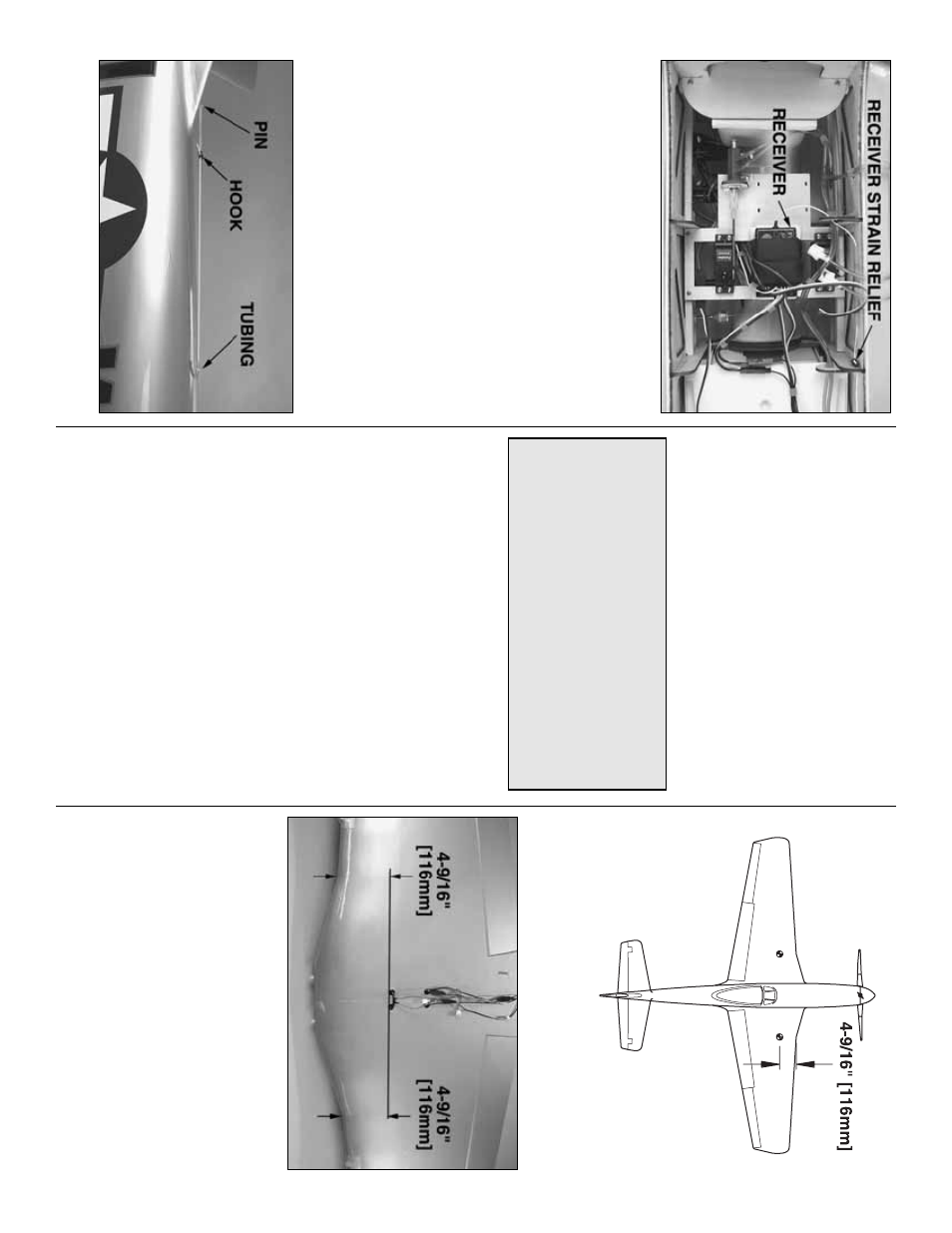
❏
4.
Mak
e
a
strain relief
for the receiv
er antenna
from a lefto
v
er ser
v
o
ar
m.
Install the str
ain relief near
the end of the antenna where it enters the receiv
er
.
Dr
ill 3/32" holes through a f
e
w of the f
o
rm
ers to guide
the receiv
er antenna a
w
a
y
from the ser
v
os and
wires
.
Guide the antenna through a hole in the
fuselage insulated with a piece of lefto
v
e
r air line or
fuel tubing.
Connect the end of the antenna to a pin
stuc
k into the fin via a r
u
b
ber band and a
hook
made
from another lefto
v
er ser
v
o
ar
m.
Balance the Model
(C.G.)
The model should be in
read
y-to-fl
y
condition with
all of the systems in place including the landing
gear
, engine
, propeller
, spinner
, etc.
It is advisab
le to
ha
v
e
tw
o people to balance the model—one to hold
the model (or place it on the balance stand) and one
to vie
w it from the side to see if the stabiliz
er is le
v
el.
❏
1.
If using a Great Planes C
.G.
Machine to balance
the model, set the r
ulers to
4-9/16" [116mm]
and
adjust the bases so the upr
ight rods are spaced
appro
ximately 22-1/2" [570mm] apar
t (to suppor
t the
wing at the
“break”
in the leading edge as sho
wn in
the sk
etch).
If not using a C
.G.
machine
, accur
ately
mar
k the C
.G.
on the top of both sides of the wing
4-9/16" [116mm]
from the
“break”
in the leading
edge with a fine-point f
elt-tip pen.
Connect the mar
k
s
with a str
ip of 1/8" [3mm] (or narro
w
er) tape
.
(Y
ou will
be ab
le to f
eel the tape line when lifting the model
upside-do
wn with y
our fingers
.)
More than an
y other f
actor
, the
C.G.
(balance
point) can ha
v
e
the
greatest
eff
ect on ho
w a
model flies and ma
y deter
mine whether or not
y
our first flight will be successful.
If y
ou v
alue this
model and wish to enjo
y it f
or man
y flights
,
DO
NO
T O
VERLOOK
THIS IMPOR
T
ANT
PR
OCEDURE.
A model that is not proper
ly
balanced will be unstab
le and possib
ly unfly
ab
le
.
- 38
-