Top Flite TOPA0700 User Manual
Page 36
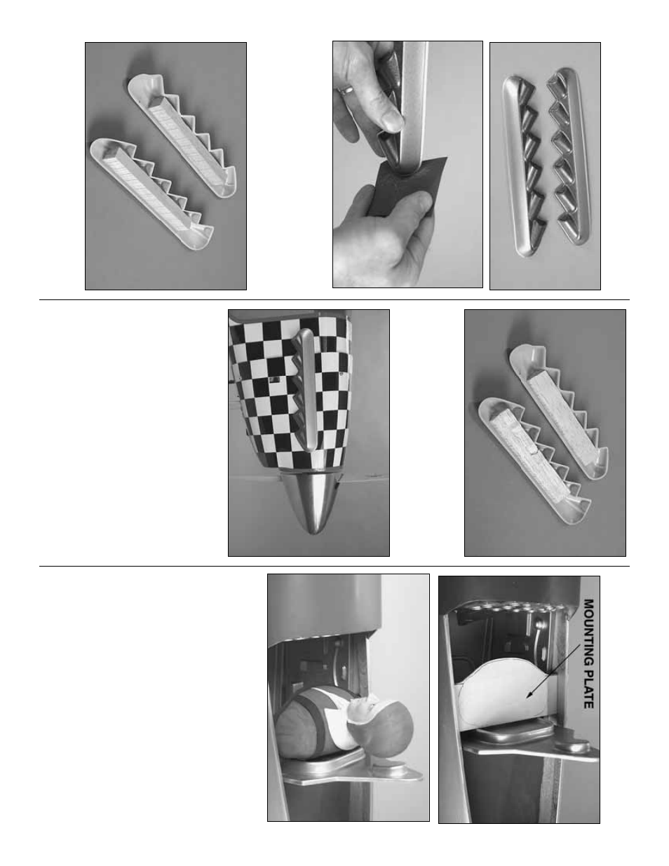
Engine Exhaust
❏
1.
Cut out the molded plastic
engine e
xhaust
pipes
lea
ving an appro
ximately 3/32" [2mm] r
idge all
the w
a
y around.
T
rue the edges with a bar sander
and 180-g
rit sandpaper
.
Smooth the edges with 400-
g
rit sandpaper
.
❏
2.
Use medium CA to glue a 3/4" x 3/4" x 7" [20 x
20 x 180mm] balsa stic
k to the inside of each
e
xhaust pipe
.
❏
3.
T
rim the balsa stic
ks until the
y are e
v
en with the
gluing surf
ace of the e
xhaust pipes
.
Ref
er to this photo f
or the f
ollo
wing three steps.
❏
1.
T
est fit one of the e
xhaust pipes to the co
wl
where sho
wn in the photo
.
Use coarse sandpaper to
sand the co
wl where the balsa inside the pipes will
be glued on.
❏
2.
Apply a coating of microballoons mix
ed with 30-
min
ute epo
xy to the balsa stic
k inside one of the
pipes
.
P
osition the pipes on the co
wl and hold them
do
wn with r
u
b
ber bands or masking tape
.W
ipe a
w
a
y
e
xcess epo
xy bef
ore it hardens
.
❏
3.
After the epo
xy from the pre
vious step hardens
,
glue the other set of e
xhaust pipes to the other side
.
Canop
y and pilot
❏
1.
Deter
mine ho
w y
ou will be mounting the pilot.
In
the model depicted in the man
ual, a
Williams Brother’
s
#625 3" (1/4-scale) Standard pilot (WBRQ22625) w
a
s
used and mounted to a mounting plate made from 1/8"
[3mm] lite-ply (not included) that w
as painted b
lac
k.
T
e
st
fit the pilot and place the canop
y on the fuselage
.Mak
e
cer
tain the pilot does not contact the canop
y.
Mak
e
adjustments as necessar
y.
❏
2.
P
aint the pilot and mounting plate if used.
Acr
ylic modeling paint (f
ound at hob
b
y
shops and
cr
aft stores) is suitab
le
.
❏
3.
Securel
y
mount the mounting plate and pilot in
the coc
kpit.
- 36
-