Top Flite TOPA0700 User Manual
Page 27
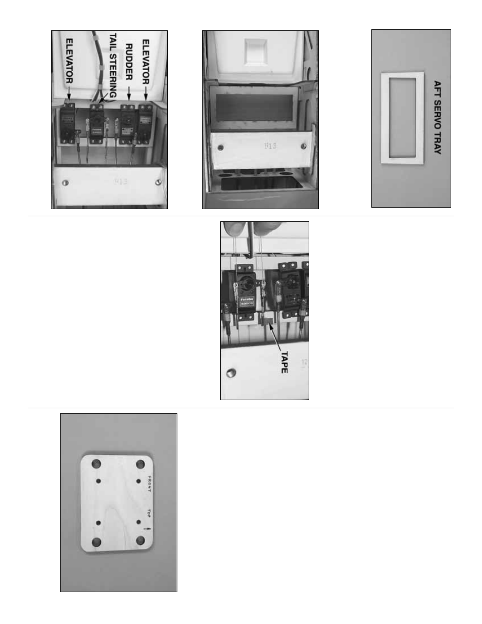
❏
4.
Glue together both 1/8" [3mm] plyw
ood
aft
ser
v
o
tra
ys
.T
est fit the tw
o ele
v
ator
, one r
udder and
one tail wheel ser
v
o
in the tr
a
y.
Mak
e an
y
adjustments required so the ser
v
o
s fit.
❏
5.
Place the ser
v
o
tr
a
y
in the fuselage
.
Ref
er to this photo while hooking up the ser
v
os.
❏
6.
Place all f
our ser
v
os in the ser
v
o
tr
a
y.
M
ak
e
three one-ar
m ser
v
o
ar
ms and one tw
o-ar
m ser
v
o
ar
m from the ar
ms that came with y
our ser
v
o
s
.
Place
the ar
ms on the ser
v
os as sho
wn in the photo
.
❏
7.
The same as w
as done f
or the aileron and flap
pushrods
, mar
k the ele
v
a
tor and r
udder pushrods
where the
y are to be cut f
or solder
ing on the cle
vises
.
One at a time
, unthread each pushrod from the cle
vis
on the control hor
n, remo
v
e
the pushrod from the
fuselage
, cut it to the correct length, then solder on
the cle
vis
.
Reinstall the pushrod from the front, then
connect them to the ser
v
o
ar
ms and control hor
ns
.
Don’t f
orget to use a silicone retainer on all the
cle
vises and to install 4-40 n
uts on the pushrods
ahead of the thread-on cle
vises
.
❏
8.
Connect the tw
o cle
vises with the threaded,
br
ass couplers and n
uts on them to both ends of the
tail steer
ing ser
v
o
ar
m.
Put a small piece of tape on
one of the pull/pull cab
les coming from the tail
steer
ing ar
m.
Center the tail wheel and slide the tape
along the cab
le to mar
k where it will be looped-o
v
e
r
to go into the br
ass coupler
.
❏
9.
T
a
k
e
the ser
v
o
ar
m off the tail steer
ing ser
v
o
and disconnect the cab
le from the ball link on the
steer
ing ar
m.
Pull the cab
le up through the guide
tube
.
Use the tape as a ref
erence f
or where to bend
the cab
le to loop it through the br
ass coupler
.
Secure
the cab
le to the coupler with a s
w
age
.
❏
10.
Guide the looped end of the cab
le bac
k do
wn
through the guide tube and reconnect it to the ball
link ball on the steer
ing ar
m.
Mar
k and connect the
other cab
le to the br
ass coupler on the other side of
the ser
v
o
ar
m same w
a
y.
❏
11.
Mar
k the hole locations f
o
r the ser
v
o mounting
scre
ws on the ser
v
o
tr
a
y.
R
emo
v
e the ser
v
o
tr
a
y, then
dr
ill 1/16" [1.6mm] holes at the mar
k
s
.
Scre
w
, then
remo
v
e
a scre
w in each hole
.
Add a f
e
w drops of thin
CA and allo
w to harden.
❏
12.
Securely glue the ser
v
o
tr
a
y
in the fuselage
with 30-min
ute epo
xy
.
M
ount the ser
v
os in the tr
a
y
and hookup the pushrods
.
We
’ll finish up the rest of the radio installation
and mount the components f
or the air system
after the engine has been mounted.
Mount the engine
The f
ollo
wing instr
uctions illustr
ate ho
w to mount a
U
.S
.
Engines 41cc gas engine
.
A
Great Planes
Gasoline Engine Mount (GPMG2000—not included)
and the par
ts included with this model will pro
vide
the correct alignment and spacing.
If not using a
U
.S
.
Engines 41cc engine
, use the appropr
iate
hardw
are to mount y
our engine (or engine mount)
centered on the hor
iz
ontal and v
e
rtical alignment
mar
ks on the fire
w
all.
Note that the bac
k of the
spinner bac
kplate should be 7-1/2" to 7-3/4" [190 to
200mm] from the fire
w
all.
❏
1.
If using a U
.S
.
Engines 41cc engine
, use the
engine mount template
in the bac
k of the man
ual to
mar
k the engine mounting bolt locations on a Great
- 27
-