Top Flite TOPA0700 User Manual
Page 21
❏
9.
Bolt the wing to the fuselage with tw
o 1/4-20 x
2" [50mm] n
ylon wing bolts
.
Center the stab in the
fuselage
.
Stand appro
ximately ten f
eet behind the
model and vie
w the stab and wing.
If the stab and
wing align with each other
, proceed to the ne
xt step
.
If the stab and wing do not align, b
ut are close
, place
a small w
eight on the
“high side”
of the stab to see if
y
ou can br
ing it into alignment.
If w
eight is not
enough, remo
v
e the stab from the fuselage and
lightly sand the slots in the fuselage as necessar
y to
align the stab with the wing.
Reinser
t the stab and
chec
k
the alignment.
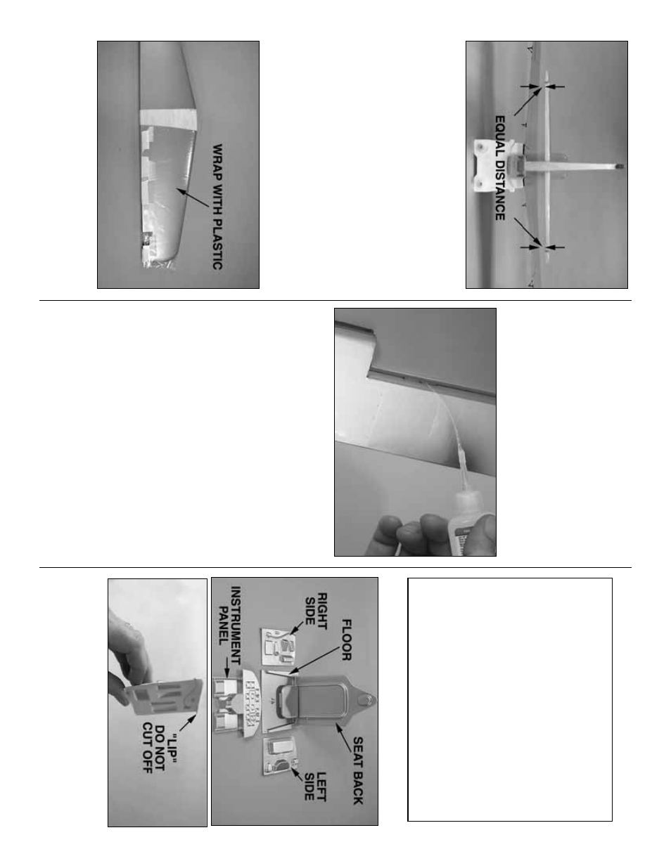
❏
10.
When ready to per
manently glue the stab into
the fuselage
, wr
ap one side of the stab with a plastic
bag or w
ax paper
.
This will protect the stab from
epo
xy when sliding it into the fuse
.
❏
11.
Thor
oughl
y
coat the slot in the fuselage
where the stab fits and the top and bottom of the
stab where it joins the fuselage with 30-min
ute
epo
xy
.
Slide the stab into position.
Remo
v
e
the
protectiv
e plastic wr
apped around the stab in the
pre
vious step
.
W
ipe off e
xcess epo
xy
.
Rechec
k the
stab alignment the same as w
as done in the
pre
vious steps
.
Do not disturb the fuse until the
epo
xy has fully hardened.
❏
12.
Stic
k a
T
-pin through the middle of f
our hinges
to k
eep them centered.
After the epo
xy on the stab
has hardened, join the ele
v
ators to the stab with the
hinges and remo
v
e
the
T
-pins
.
M
ak
e a small gap
betw
een the stab and ele
v
ators—just enough to see
light through or to slip a piece of paper through.
Allo
wing enough time betw
een drops to allo
w the CA
to soak in, add six to eight drops of thin CA to
both
sides
of all the hinges
.
Hint:
Use a CA applicator tip
so the CA can be applied directly to the hinges
.
❏
13.
Join the r
udder to the fin with the hinges and
glue them in the same w
a
y.
Install the coc
kpit
Ref
er to this photo while w
o
rking on the coc
kpit.
❏
1.
Use small scissors or cur
v
ed-tip scissors (such
as K
y
osho
®
or Great Planes) to cut out the coc
kpit
sides
.
Do not cut the
lip
from top
.
T
rim the aft edge
(the edge with the angle) of both sides so the
y will fit
betw
een the f
o
rmers in the coc
kpit.
Installation of the included semi-scale coc
kpit kit is
optional.
If y
ou pref
er not to install the complete
coc
kpit, all that has to be done is to paint the
e
xisting balsa coc
kpit area and add the instr
ument
panel decal.
Should y
ou decide to install the
coc
kpit, k
eep in mind that although this model is an
ARF
, the included coc
kpit kit is a star
ting platf
or
m.
Should y
ou wish to add more detail, study photos
of a full-siz
e P-51 coc
kpit, then decide ho
w to
proceed.
Man
y of the mechanisms can be added
or enhanced simply with a fine paint br
ush and a
selection of plastic model paint.
Whate
ver pilot y
o
u
decide to use should be test fit bef
ore gluing an
y of
the coc
kpit par
ts into position in case an
y
modifications are required.
- 21
-