Top Flite TOPA0700 User Manual
Page 28
Planes Gasoline Engine Mount.
Dr
ill 17/64" [6.8mm]
(or 9/32" [7.2mm]) holes at the mar
ks
.
Cut off the
bottom of the mount as indicated on the template
.
Mar
k the
top
and
fr
ont
of the mount as sho
wn.
❏
2.
Remo
v
e
the m
uffler and carb
uretor from the
engine
.
This will f
acilitate mounting the engine and
fitting the co
wl.
❏
3.
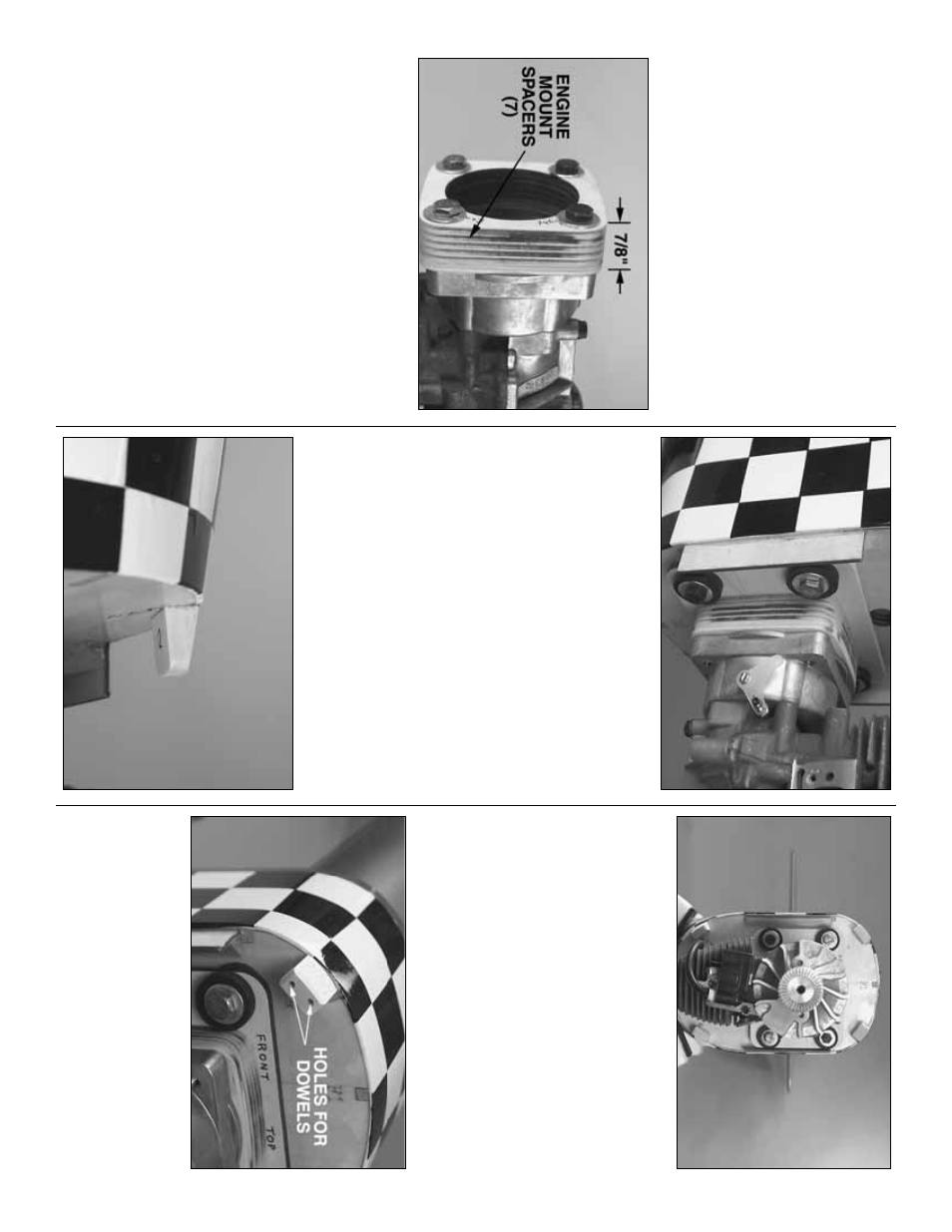
The U
.S
.
Engines 41cc is to be spaced
appro
ximately 7/8" [22mm]
fr
om the mount
(not
from the fire
w
all).
If y
our U
.S
.
Engine came with the
1/2" [13mm] b
lac
k, plastic engine mount spacer
, glue
together
three
1/8" [3mm] plyw
ood
engine mount
spacer
s
.
If y
our U
.S
.
Engine did
not
come with the
b
lac
k, plastic spacer
, glue together
se
ven
1/8" [3mm]
plyw
ood engine mount spacers
.
This is most easily
done b
y
lightly coating the spacers with 30-min
ute
epo
xy and using the bolts that came with the Great
Planes Gasoline Engine Mount to bolt the spacers to
the engine—do not o
v
er tighten the bolts
, thus
def
or
ming the plyw
ood.
Note
:
The
straight
edge of
the spacers goes on the r
ight side of the fuselage
.
❏
4.
After the epo
xy on the engine mount spacer
has hardened, remo
v
e it from the engine and sand
the edges e
v
en and smooth.
❏
5.
Use 1/4-20 x 1-1/2" [40mm] bolts and 1/4"
[6.4mm] w
ashers (not included) to mount the engine
with the plyw
ood spacers and the plastic spacer (if
included with the engine) to the engine mount.
Bolt
the engine mount to the fire
w
all using the r
u
b
ber
b
ushings
, w
ashers and bolts that came with it.
Mount the co
wl
Ref
er to these photos f
or the f
ollo
wing tw
o steps.
❏
1.
Use a hob
b
y
knif
e and sandpaper to shape f
our
of the six supplied 1/2" x 13/16" x 13/16" [12 x 20 x
20mm] hardw
ood
co
wl mounting b
loc
ks
to match
the shape of the fuselage and the co
wl.
❏
2.
Thor
oughl
y
roughen the fire
w
all in the f
our
locations where the co
wl mounting b
loc
ks will go
.
Coat the end of the b
loc
ks and the fire
w
all with
30-min
ute epo
xy
.
Allo
w the epo
xy to
“tac
k up”
so the
b
loc
ks w
on’t f
all off
, then place them on the fire
w
all.
Contin
ue to monitor and reposition the b
loc
ks as
necessar
y until the
y will sta
y in place
.
Allo
w the
epo
xy to fully harden.
❏
3.
After the epo
xy from the pre
vious step has
hardened, dr
ill tw
o 1/8" [3.2mm] holes through the
b
loc
ks and the fire
w
all.
Cut eight 1-1/4" [30mm]
pieces from the 1/8" x 12" [3.2 x 300mm] hardw
ood
do
w
el.
Coat the do
w
els and the holes in the
mounting b
loc
ks with 30-min
ute epo
xy
, then use a
hammer to tap the do
w
els all the w
a
y in.
- 28
-