Top Flite TOPA0700 User Manual
Page 40
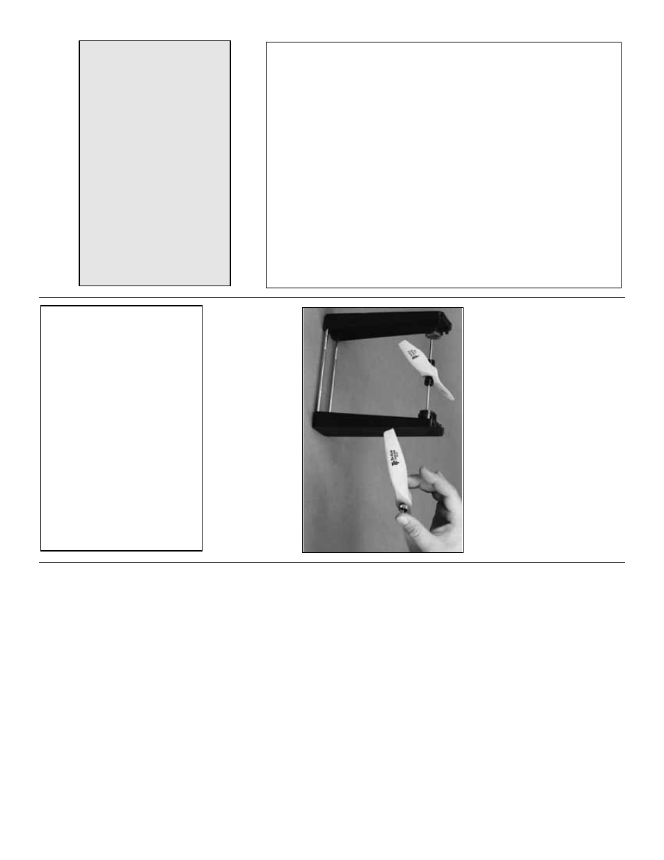
Balance Pr
opeller
s
Carefully balance y
our propeller and spare
propellers bef
ore y
ou fly
.An unbalanced prop can be
the single most significant cause of vibr
ation that
can damage y
our model.
Not only will engine
mounting scre
ws and bolts loosen, possib
ly with
disastrous eff
ect, b
ut vibr
ation ma
y also damage
y
our r
adio receiv
er and batter
y.
Vibr
ation can also
cause y
our fuel to f
oam, which will, in tur
n, cause
y
our engine to r
u
n hot or quit.
W
e
use a
T
op Flite Precision Magnetic Prop
Balancer
™
(T
OPQ5700) in the w
o
rkshop and k
eep a
Great Planes Finger
tip Prop Balancer (GPMQ5000)
in our flight bo
x.
CHECK LIST
❏
1.
Fuelproof all areas e
xposed to fuel or e
xhaust
residue such as the co
wl mounting b
loc
ks
,
wing saddle area, etc.
❏
2.
Chec
k the C
.G.
according to the measurements
pro
vided in the man
ual.
❏
3.
Be cer
tain the batter
y and receiv
er are
securel
y
mounted in the fuselage
.Simply stuffing them into
place with f
oam r
u
b
ber is not sufficient.
❏
4.
Extend the receiv
er antenna and mak
e sure it
has a str
ain relief inside the fuselage to k
eep
tension off the solder joint inside the receiv
er
.
❏
5.
Balance the model
later
ally
as e
xplained in
the instr
uctions
.
❏
6.
Use threadloc
king compound to secure cr
itical
fasteners such as the n
uts that hold the wheel
axles to the str
uts
, scre
ws that hold the
carb
uretor ar
m (if applicab
le), set scre
ws that
hold the tail gear components
, etc.
❏
7.
Add a drop of oil to the axles so the wheels will
tur
n freely
.
❏
8.
Mak
e
sure all hinges are
securel
y
glued in place
.
❏
9.
Reinf
orce holes f
or w
ood scre
ws with thin CA
where appropr
iate (ser
v
o mounting scre
ws
,
co
wl mounting scre
ws
, etc.).
❏
10.
Confir
m that all controls oper
ate in the correct
direction and that the thro
ws are set up
according to the man
ual.
❏
11.
Mak
e
sure there are silicone retainers on all
the cle
vises and that all ser
v
o
ar
ms are
secured to the ser
v
os with the scre
ws included
with y
our r
adio
.
❏
12.
Secure connections betw
een ser
v
o
wires and
Y
-connectors or ser
v
o
e
xtensions
, and the
connection betw
een y
our batter
y
pac
k and the
on/off s
witch with vin
yl tape
, heat shr
ink tubing
or special clips suitab
le f
or that pur
pose
.
❏
13.
Mak
e
sure none of the ser
v
o
wires or air lines
interf
ere with an
y mo
ving par
ts (ser
v
o
ar
ms
,
pushrods
, retr
acts
, etc.).
❏
14.
Mak
e
sure the fuel lines are connected and
are not kink
ed.
❏
15.
Securely tighten the propeller n
ut.
Remo
ve the
3mm scre
ws that hold the spinner cone to the
bac
kplate
.
Add a small drop of thread loc
king
compound to the scre
ws
, then reinstall the scre
ws
.
Dur
ing the last f
e
w moments of prepar
ation y
our
mind ma
y be else
where anticipating the
e
xcitement of the first flight.
Because of this
, y
o
u
ma
y be more lik
ely to o
v
er
look cer
tain chec
ks
and procedures that should be perf
or
med bef
ore
the model is flo
wn.
T
o
help a
v
oid this
, a chec
klist
is pro
vided to mak
e sure these impor
tant areas
are not o
v
er
look
ed.
Man
y are co
v
ered in the
instr
uction man
ual, so where appropr
iate
, ref
er to
the man
ual f
or complete instr
uctions
.
Be sure to
chec
k the items off as the
y are completed (that’
s
wh
y it’
s called a
chec
k
list!
).
IMPOR
T
ANT
:
The
T
op Flite Giant P-51D
Mustang ARF has been
e
xtensivel
y
flo
wn and
tested to arr
iv
e
at the thro
ws at which it flies best.
Flying y
our model at these thro
ws will pro
vide
y
ou with the g
reatest chance f
or successful first
flights
.
If,
after y
ou ha
v
e
become accustomed to
the w
a
y the Mustang flies
, y
ou w
ould lik
e to
change the thro
ws to suit y
our taste
, that is fine
.
Ho
w
e
v
e
r, too m
uch control thro
w could mak
e the
model difficult to control, so remember
,
“more is
not alw
a
ys better
.”
These are the recommended control surf
ace thro
ws:
High Rate
Lo
w Rate
ELEV
A
T
O
R
9/16" up
3/8" up
[14mm]
[10mm]
9/16" do
wn
3/8" do
wn
[14mm]
[10mm]
R
UDDER
1-1/2" r
ight
1" r
ight
1-1/2" left
1" left
[38mm]
[25mm]
AILER
ONS:
3/4" up
1/2" up
[19mm]
[13mm]
5/8" do
wn
3/8" do
wn
[16mm]
[10mm]
Half Rate
Full Rate
FLAPS:
1-3/16" [30mm]
2-1/8" [55mm]
Note:
If flying the model at the f
orw
ard C
.G.
location, y
ou should land with the ele
v
ator thro
ws
set to the
high
ra
te
.If the model is nose-hea
vy the
lo
w-r
a
te thro
ws ma
y not pro
vide enough control to
flair upon landing.
- 40
-