Top Flite TOPA0700 User Manual
Page 32
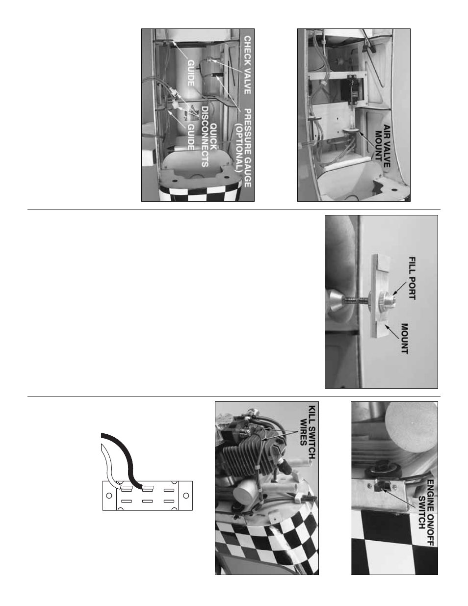
Hook up the air lines
Ref
er to this photo while hooking up the air lines.
❏
R1.
Use epo
xy to glue the plyw
ood
air v
alve
mount
to the f
orw
ard ser
v
o
tr
a
y.
After the epo
xy
hardens
, mount the air v
a
lv
e to the air v
alv
e mount.
❏
R2.
Use the remaining air line and tw
o
T
-fittings
to connect the
fill por
t,
c
hec
k v
alve
and
pressure
gaug
e
(optional) to the air tank.
Also connect the
quic
k disconnects
to the air lines coming from the
tail gear air lines via tw
o
T
-fittings
.
The remaining,
open end of these
T
-fittings will be connected to the
air v
a
lv
e
.
Connect another line to the
T
-fitting
betw
een the fill por
t and the chec
k v
alv
e
.This line will
be connected to the air v
alv
e
.
Note:
Use the plyw
ood
air line guides
to k
eep the air lines neat and tidy and
a
w
a
y
from other w
o
rking components (such as
ser
v
o
s
, pushrods
, etc.).
❏
R3.
Mount the fill por
t and pressure gauge (if
used) to the fuselage side
.
The fill por
t can be
mounted flush to the outside of the fuselage via a
mount made from plyw
ood (not supplied).
❏
R4.
Connect the air v
alv
e ser
vo
to the air v
alv
e using
a 2-56 x 4" [100mm] pushrod and a n
ylon cle
vis
.
Connect the pushrod to the ser
vo
ar
m with a
“Z”
bend.
Connect the remaining air lines to the air v
alv
e
.
Mount the kill s
witc
h
(f
or spark ignition engines onl
y)
As stated in the IMAA Saf
ety Code
, all magneto spar
k
ignition engines m
ust ha
ve
a man
ually oper
ated, coil-
g
rounding s
w
itch to stop the engine and pre
vent
accidental star
ting.
A .3 Amp slide s
w
itch, 16 gauge
wire and tw
o spade ter
m
inals w
e
re purchased at the
local Radio Shac
k
®
for this pur
pose
.
T
hese common
components should also be a
vailab
le at an
y hardw
are
or home impro
vement store
.
❏
1.
Mount the s
witch in a location where it will be
easily accessib
le from outside the model.
❏
2.
Deter
mine the correct length of the wires
kno
wing that the
y m
ust not contact the m
uffler or
engine
.
Cut the wires to the correct length, then
solder the wires to the s
witch and spade ter
minals
.
❏
3.
Connect the ter
m
inals to the engine
, making
cer
tain the wires will not contact the engine or m
uffler
.
BO
TT
OM OF SWITCH
SOLDER THE
WIRES WHERE
SHO
WN
- 32
-