Top Flite TOPA0700 User Manual
Page 37
❏
4.
W
ash the canop
y in w
a
rm
, soap
y w
ater
, then
dr
y it off
.
Place the canop
y on the fuselage
.
B
e
cer
tain it is centered from side-to-side
.
T
empor
ar
ily
tape the canop
y into position.
Dr
ill f
our e
v
enly spaced
1/16" [1.6mm] holes through both sides of the
canop
y and the coc
kpit sides
.
T
ak
e the canop
y off
and enlarge the holes
in the canop
y onl
y
with a
3/32" [2.4mm] dr
ill.
Mount the canop
y with eight #2 x
3/16" [4.8mm] scre
ws
.
❏
5.
Remo
ve
the canop
y
and scre
ws
.
Add a f
e
w drops
of thin CA to the holes to harden the threads
.
Allo
w the
CA to fully harden, then remount the canop
y.
Appl
y the decals
1.
Use scissors or a shar
p hob
b
y
knif
e to cut the
decals from the decal sheets
.Where possib
le
, round
the cor
ners so the
y w
on’t catch and lift while
cleaning and handling the model.
2.
Be cer
tain the model is clean.
Prepare a dishpan or
small b
u
ck
et with a mixture of liquid dish soap and w
a
rm
w
a
ter—about 1/2 teaspoon of soap per gallon of w
ater
.
Submerse one of the decals in the solution and peel off
the paper bac
king.
Note:
Ev
en though the decals ha
ve
a
“stic
ky-bac
k”
and are not the w
a
ter tr
ansf
er type
,
submersing them in soap and w
ater allo
ws accur
ate
positioning and reduces air b
u
b
b
les under
neath.
3.
P
osition the decal on the model where desired.
Holding the decal do
wn, use a paper to
w
el to wipe
most of the w
ater a
w
a
y.
4.
Use a piece of soft balsa or something similar to
squeegee remaining w
ater from under the decal.
Apply the rest of the decals the same w
a
y.
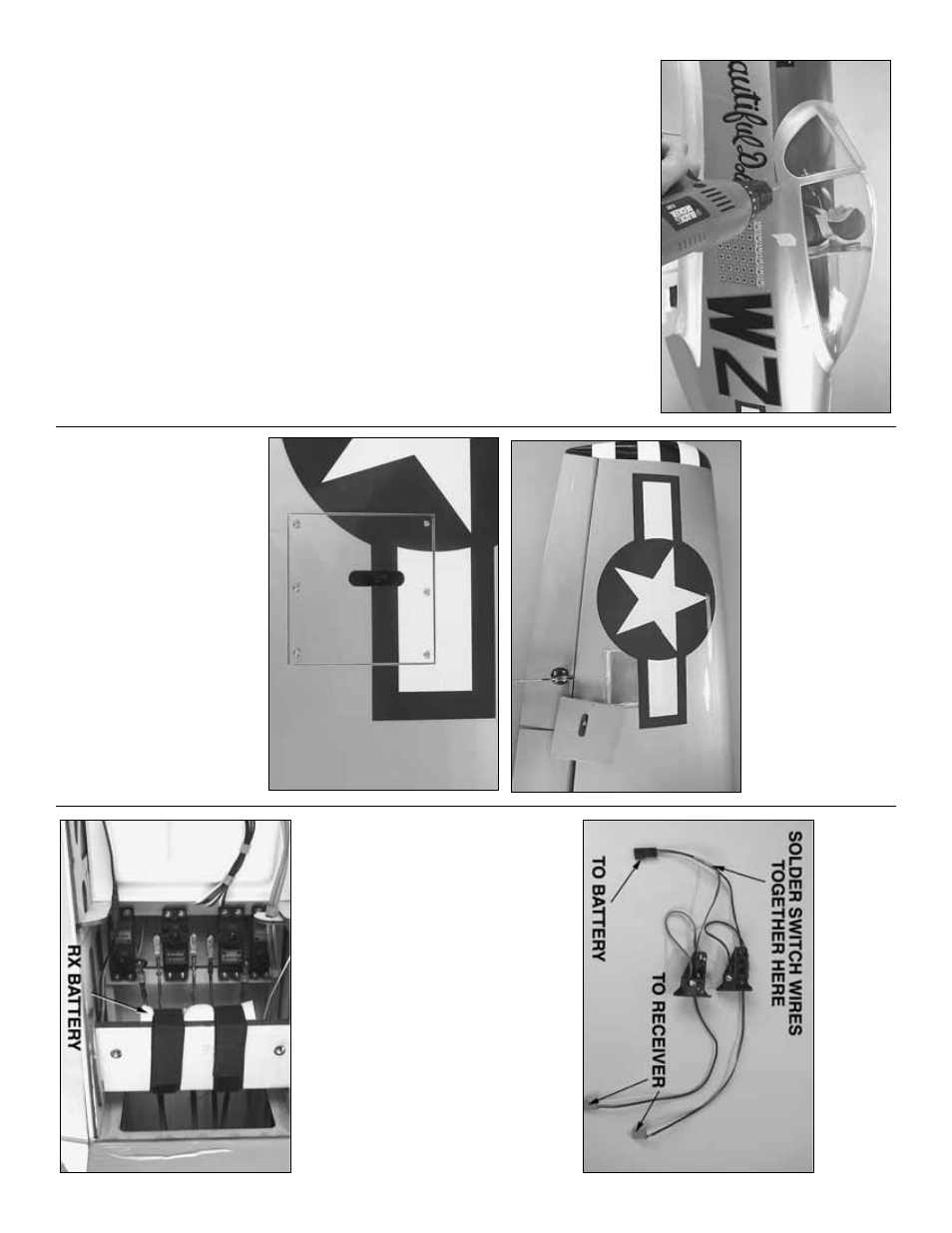
❏
Note:
T
o
apply the stars a
n
d
bars on the bottom of
the r
ight wing, remo
v
e the aileron ser
v
o
hatch.
Apply
the decal.
Squeegee the w
ater out, then cut along
the edges of the hatch.
P
osition the hatch.
Apply the
cut off por
tion of the decal to the hatch.
GET
THE MODEL READ
Y
T
O
FL
Y
Complete the radio installation
❏
1.
Mount the receiv
er on/off s
witch in a str
ategic
location where it w
on’t interf
ere with an
ything inside
the fuselage and where it will not get coated with
engine e
xhaust outside the fuselage
.
Due to the
higher le
v
els of vibr
ation from some gas engines
, tw
o
s
witches ma
y be used f
or redundancy
.
If using tw
o
s
witches
, solder the wires together as sho
wn.
A
Great Planes Switch & Charge J
a
c
k
Mounting Set
(GPMM1000) w
as also used f
or charging and
v
oltage monitor
ing from outside the fuselage
.
- 37
-