Top Flite TOPA0700 User Manual
Page 26
x 1-9/16" [1 x 10 x 40mm] plyw
ood
tail g
ear door
stop
to the inside of the sheeting on the bottom of
the fuselage
.
These will k
eep the doors from closing
too f
a
r.
Hook tw
o small r
u
b
ber bands included with
this kit onto both pair of r
u
b
ber band hooks
.
❏
R18.
Use the air pump that will be used to
pressur
iz
e the air tank or a can of compressed air to
retr
act and e
xtend the tail gear a f
e
w times to mak
e
sure e
v
er
ything oper
ates correctly
.
Mak
e
adjustments where required.
Skip ahead to
“Hook up
the ele
v
ators and r
udder”
on this page
.
Mount the fix
ed tail g
ear
❏
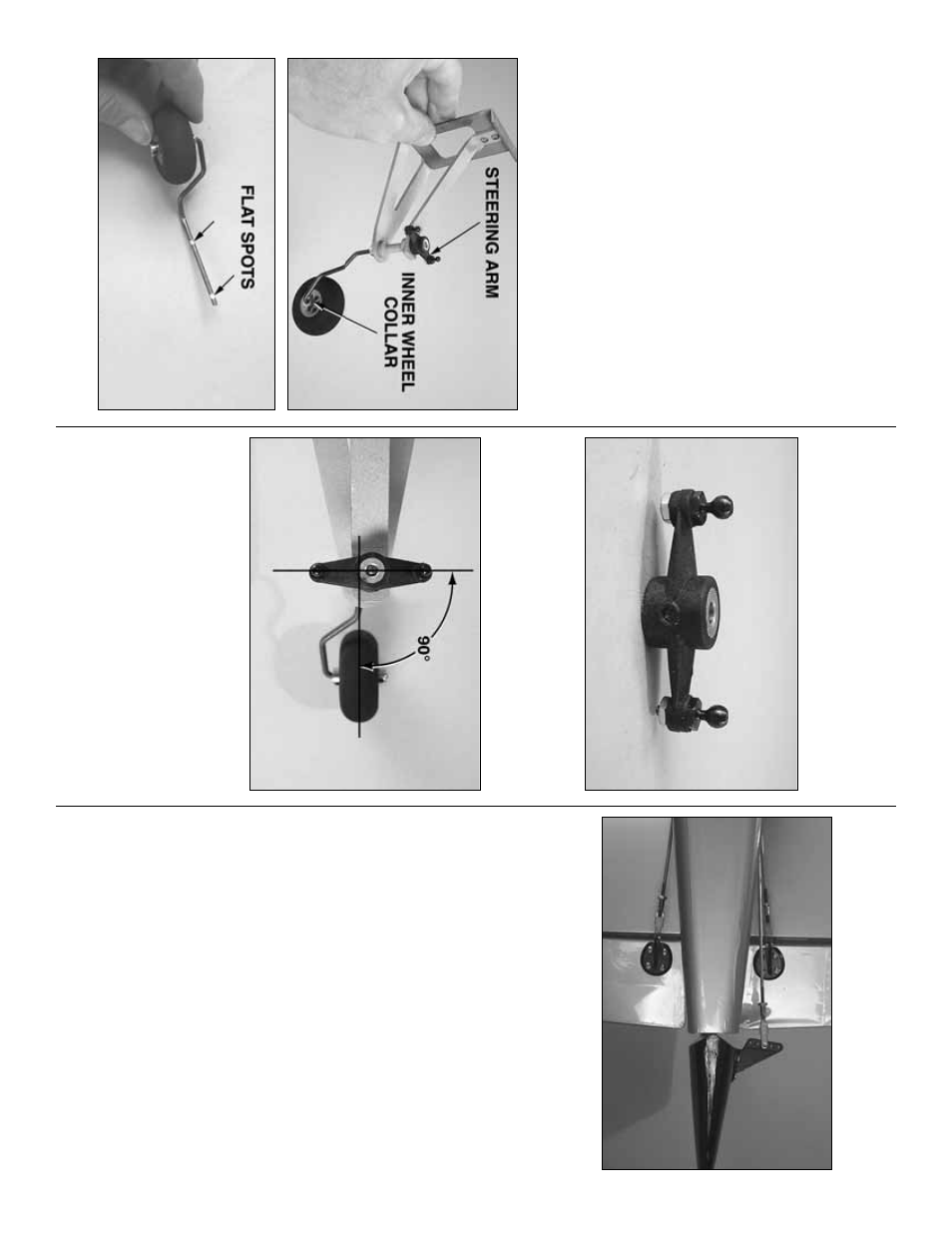
F1.
Cut the co
v
e
ring from the tail gear opening in
the bottom of the fuselage
.
Ref
er to this photo f
or the f
ollo
wing three steps.
❏
F2.
File flat spots on the tail gear wire f
or the set
scre
w in the outer wheel collar that holds on the wheel,
and f
o
r the set scre
ws in the wheel collar
steering arm
that hold the tail gear wire in the tail gear mount.
Mount
the tail wheel with tw
o wheel collars and set scre
ws
using a drop of thread loc
king compound.
❏
F3.
Enlarge the holes in the steer
ing ar
m with a
5/64" [2mm] or 3/32" [2.4mm] dr
ill bit.
Mount a 2-56
ball link ball to each ar
m with a 2-56 n
ut and a drop
of threadloc
k
e
r.
❏
F4.
Assemb
le the tail gear
.
Be cer
tain to use
thread loc
king compound on all the set scre
ws
.
A
lso
note that the steer
ing ar
m should be per
pendicular to
the tail wheel.
P
erf
orm steps 5,
6,
7 & 8 and steps 14,
15 & 16 on
pa
g
es 24 & 25 to connect the pull/pull cab
les to
the steering arm and to mount the tail g
ear in the
fusela
g
e
.
When finished,
pr
oceed to
“
Hook up
the ele
v
ator
s and rud
der
.”
Hook up the ele
v
ator
s and rud
der
Ref
er to this photo f
or the f
ollo
wing three steps.
❏
1.
Cut 6" [150mm] from the unthreaded end of tw
o
36" [910mm] wire pushrods
.
Connect the pushrods
to the middle hole in tw
o n
ylon control hor
ns with a
4-40 n
ut, threaded cle
vis and a silicone retainer
.
Slide the pushrods into the ele
v
ator pushrod tubes in
both sides of the fuselage
.
❏
2.
Mount the control hor
ns to the ele
v
ators the
same w
a
y y
ou mounted the control hor
ns on the
flaps and ailerons (b
y dr
illing 3/32" [2.4mm] holes
and using #4 x 1/2" [13mm] scre
ws—don’t f
orget to
harden the holes with thin CA
after
first installing,
then remo
ving the scre
ws).
❏
3.
Prepare the r
udder pushrod and mount the
control hor
n the same w
a
y,
only use #4 x 5/8"
[16mm] scre
ws instead of 1/2" [13mm] scre
ws
.
- 26
-