Top Flite TOPA0700 User Manual
Page 16
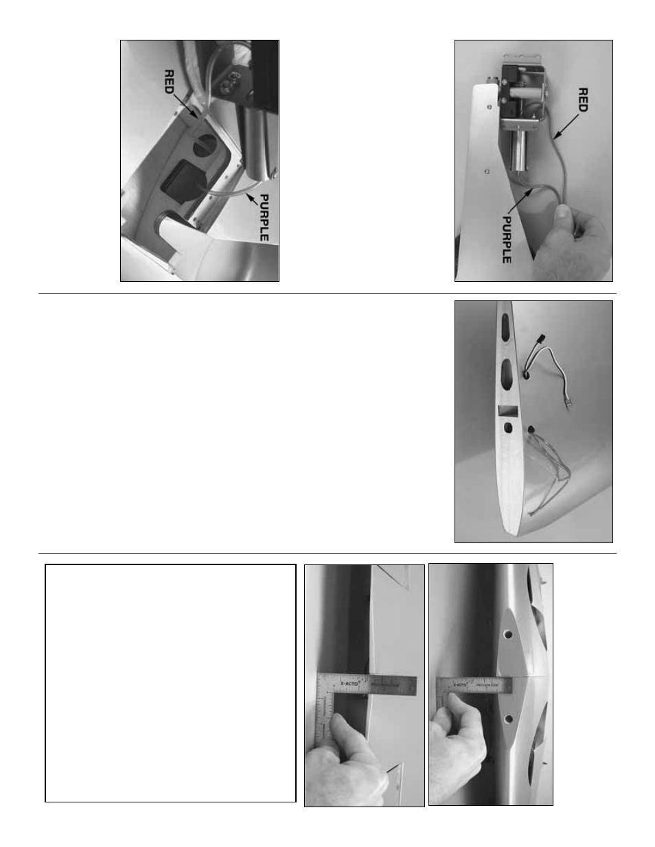
❏❏
R4.
Cut a 21" [530mm] piece of
red
air line
tubing and a 16" [400mm] piece of
purple
air line
tubing from the tubing included with the Robar
t Air
Control Kit (not included).
Connect the red line to the
outer
fitting on the air cylinder and connect the
pur
ple line to the
inner
fitting (the one directly on the
end) on the air cylinder
.
❏❏
R5.
Use a piece of m
usic wire with a hook bent
on the end or something similar to pull the air lines
through the wing.
Note that the pur
ple line goes
through the same hole that the air cylinder fits
through, and the red line goes through the round
hole behind it.
❏❏
R6.
Guide the air lines out the front hole in the
top of the wing and guide the ser
v
o
wires out the
other hole
.
❏❏
R7.
Mount the retr
act in the wing.
Use a small
scre
wdr
iv
er to mo
v
e
the end of the pushrod coming
from the air cylinder in the retr
acted (up) position so
the gear doesn’t flop around while joining the wings
.
Install the hatch.
❏
R8.
Hook up the air lines in the r
ight wing panel
the same w
a
y.
Join the wing
Note:
K
eep the retr
acts (if installed) in the retr
acted
(up) position so the
y do not e
xtend and retr
act as
y
ou handle the wing.
Because the angle of wing joiner and the angle
of the r
ibs on the end of the wing panels is
factor
y-set, chec
king the dihedr
al, as w
ould be
done on a b
uilt-up kit, is not necessar
y.
Ho
w
e
v
e
r,
for those who insist on chec
king the dihedr
al
an
yw
a
y, this ma
y be done b
y
test fitting the
wings together with the wing joiner
.
Tightly tape
the wing halv
es together
.
The joining r
ibs on the
end of both panels should fit w
ell with no gap
.
If
the wing halv
es do not fit w
e
ll, remo
v
e
an
y glue
b
lobs or other obstr
uctions that ma
y be
interf
er
ing.
Once the joining r
ibs of the tw
o wing
halv
es fit w
ell, la
y the wing upside-do
wn on y
our
w
o
rkbench.
Measure the distance betw
een the
top of the wing and the w
o
rkbench at the leading
edge
.
Also measure the distance from the top of
the wing and the w
o
rkbench at the tr
ailing edge
.
The sum of these tw
o distances should be
5-3/16" [130mm] plus or min
us 1/2" [13mm].
- 16
-