Mount the scale det ails – Top Flite TOPA0700 User Manual
Page 33
Finish the engine compar
tment
❏
1.
Use a high-speed rotar
y tool with a carbide
cutting bit to cut the hole in the co
wl f
or the
carb
uretor
.
F
or the U
.S
.
Engines 41, this procedure is
made easier if the m
uffler and v
entur
i are remo
v
ed.
Slip the co
wl into position, then, carefully vie
wing the
co
wl and the carb
uretor inside and out, mar
k
the
appro
ximate location of the cutout.
Remo
v
e
the co
wl.
Cut inside the lines star
ting with a small hole
.
F
it the
co
wl, redr
a
w
the lines
, then remo
v
e
and cut the co
wl
again.
Contin
ue to
“z
ero-in”
on the correct siz
e and
shape of the cutout b
y
fitting, mar
king and enlarging
the cutout in small increments
.
M
ount the v
entur
i
after the co
wl has been fit o
v
er the carb
.
Note:
The
v
entur
i m
ust be remo
v
ed whene
v
er the co
wl requires
remo
v
al or installation.
Dur
ing initial engine tuning
and break-in it will be best to lea
v
e
the co
wl off the
model until all adjustments ha
v
e
been made
.
When
satisfied with the perf
or
mance and reliability of the
engine
, the co
wl can be installed.
❏
2.
Cut the fuel line that goes to the carb
uretor to
the correct length, then hook up the fuel line
.
D
rill tw
o
holes through one of the remaining 1/2" x 13/16" x
13/16" [12 x 20 x 20mm] hardw
ood b
loc
ks to
accommodate the fuel lines
.
T
rim the b
loc
k to a
smaller
, finished shape
, then use epo
xy to glue the
b
loc
k to the bottom of the fire
w
all.
Guide the fueling
line and the v
ent through the holes in the b
loc
k.
❏
3.
Cut an
y other necessar
y holes in the co
wl f
o
r
the ignition s
witch, engine e
xhaust, fuel lines
, etc.
❏
4.
If y
ou ha
v
en’t already done so
, remo
v
e
the
engine and coat all bare w
ood par
ts (such as the
engine mount, engine mount spacers
, co
wl mount
b
loc
ks
, etc.) with 30-min
ute epo
xy or fuelproof paint.
Allo
w to dr
y,
then remount the engine
.
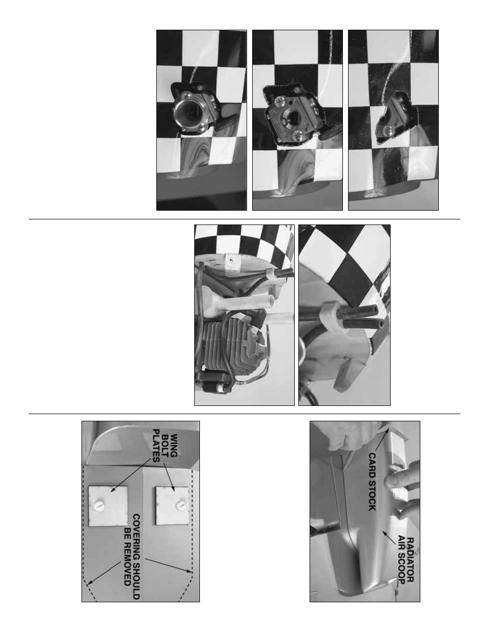
MOUNT
THE SCALE DET
AILS
Radiator air scoop
❏
1.
Mount the wing to the fuselage with the wing
bolts
.
Place the fiberglass
radiator air scoop
on the
wing.
Place a piece of thin cardstoc
k betw
een the
bac
k of the air scoop and the fuselage
.
Use a fine-
point f
e
lt-tip pen to mar
k the outline of the air scoop
onto the bottom of the wing.
❏
2.
Carefully cut the co
v
e
ring 1/32" [1mm] inside
the line
.
Be careful not to cut into the balsa.
P
eel the
co
v
e
ring from the wing.
❏
3.
Glue the plyw
ood
wing bolt plates
to the
bottom of the wing with 30-min
ute epo
xy using the
wing bolts to hold them do
wn.
(Although the co
v
e
ring
is still on the wing in this photo
, the co
v
e
ring should
be remo
v
ed from y
our wing under the air scoop
.)
- 33
-