Top Flite TOPA0700 User Manual
Page 31
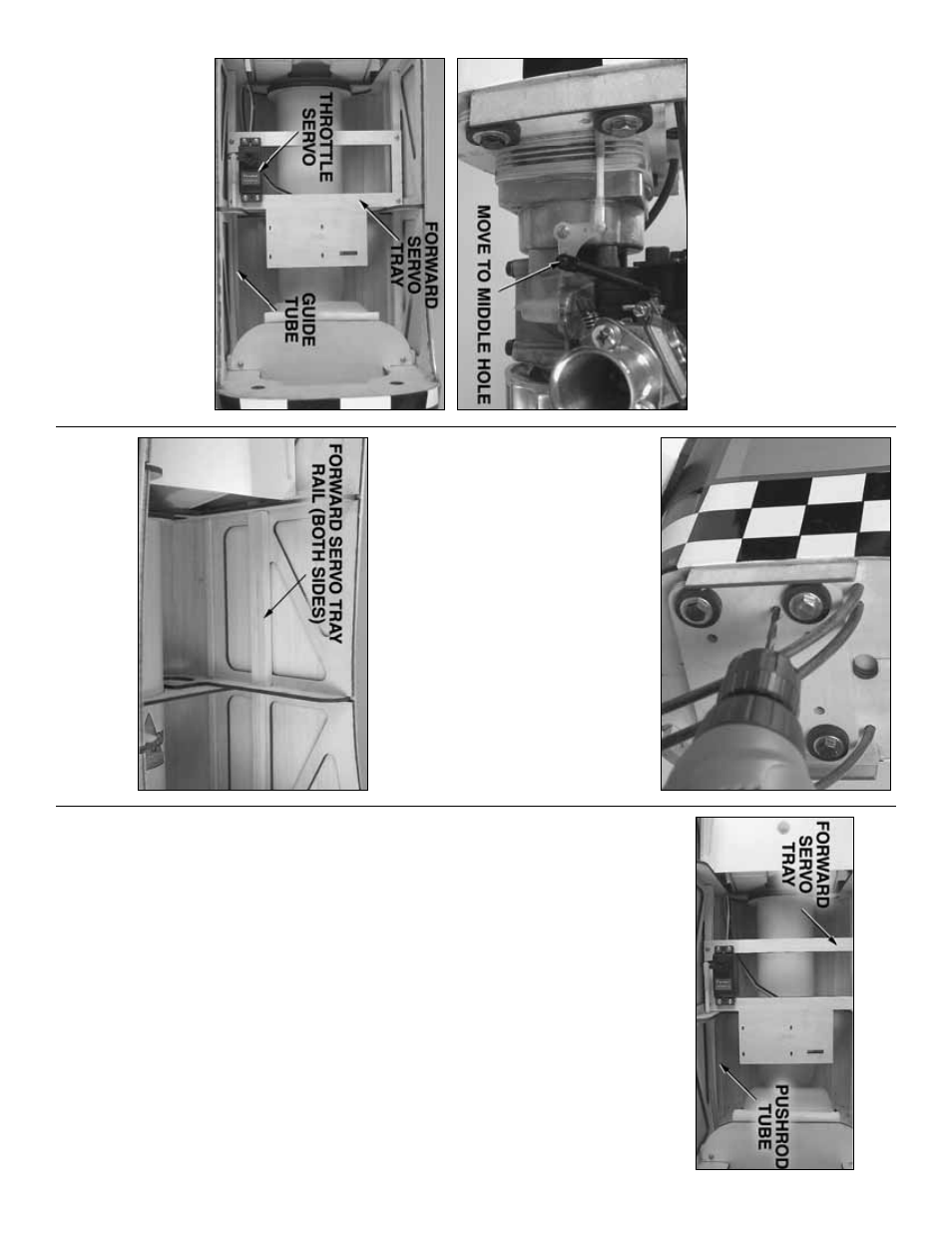
Hook up the thr
ottle
Note:
If using a
spark ignition
engine
, be cer
tain to
maintain a
minim
um distance
of 12" [300mm]
betw
e
en electronic par
ts of the r
a
dio system (ser
vo
,
receiv
er
, batter
y, etc.) and the engine
.
Also
, ne
ver use
a full-length, metallic pushrod to oper
ate the throttle
.
Ref
er to the f
ollo
wing tw
o photos while hooking
up the thr
ottle
.
❏
1.
If using a U
.S
.
Engines 41cc
, mo
v
e
the ball link
ball that w
as f
a
ctor
y-mounted on the bellcr
ank to the
middle hole
.
Connect a 0-80 ball link ball to the outer
hole on the other end of the bellcr
ank with a drop of
threadloc
k
er and a 0-80 n
ut.
❏
2.
Mar
k the engine mount where the throttle pushrod
should go through to connect to the bellcr
ank.
❏
3.
Remo
v
e
the engine from the engine mount.
Bolt
the mount to the fire
w
all without the engine
.
Being
cer
tain not to drill into the fuel tank
, dr
ill a 3/16"
[4.8mm] hole through the engine mount and the
fire
w
a
ll at the mar
k f
or the throttle pushrod.
Enlarge
the hole
in the engine mount onl
y
with a 1/4"
[6.4mm] dr
ill.
❏
4.
Remount the engine to the engine mount.
❏
5.
Cut tw
o 4-3/4" [120mm]
forwar
d ser
v
o
tra
y
rails
from the 1/4" x 1/4" x 12" [6 x 6 x 300mm]
hardw
ood stic
k.
Securely glue the r
ails to the main
side str
inger as sho
wn.
Ref
er to this photo while installing the f
orwar
d
ser
v
o
tra
y
.
❏
6.
Glue together both plyw
ood
forwar
d ser
v
o
tra
ys
.
Place the f
orw
ard ser
v
o
tr
a
y
on the r
ails
.
D
rill
four 1/16" [1.6mm] holes through the ser
v
o
tr
a
y
and
the r
ails f
or the mounting scre
ws
.
T
ak
e out the ser
v
o
tr
a
y
and enlarge the holes
in the ser
v
o
tra
y onl
y
with a 3/32" [2.4mm] dr
ill.
Mount the tr
a
y
to the r
ails
with f
our #2 x 1/2" [13mm] scre
ws
.
❏
7.
Cut the 3/16" x 24" [4.8 x 610mm] g
ra
y
pushrod
guide tube to the correct length f
o
r the throttle
.
Use
coarse sandpaper to roughen the tube so glue will
adhere where it goes through the fire
w
a
ll and
fo
rmers
.
Slide the guide tube into position.
❏
8.
Fit the throttle ser
v
o in the ser
v
o
tr
a
y.
C
ut the
white
, plastic pushrod to the correct length so it can
be connected to the throttle ser
v
o
with a n
ylon cle
vis
and to the bellcr
ank with a n
ylon ball link.
❏
9.
Thread a 2-56 x 1" [25mm] threaded rod into
both ends of the throttle pushrod.
Connect the n
ylon
ball link to one end of the rod, then slide the rod into
the guide tube from the front.
❏
10.
Connect the n
ylon cle
vis to the threaded rod
on other end of the pushrod.
Connect the cle
vis to
the throttle ser
v
o
ar
m with a silicone retainer
.
Use
medium CA to glue the guide tube to the fire
w
all and
the f
o
rmers
.
❏
11.
Remo
v
e
the f
orw
ard ser
v
o
tr
a
y.
Add a f
e
w
drops of thin CA to the holes in the ser
v
o
tr
a
y
r
ails
and allo
w to harden.
Mount the throttle ser
v
o to the
tr
a
y
as w
ell.
Remount the ser
v
o
tr
a
y.
- 31
-